Appendix A
Installation manual to TCS5500 Appendix A ● 83
be disabled if the corresponding microphone is activated.
A supplementary RJ45 connector must be provided.
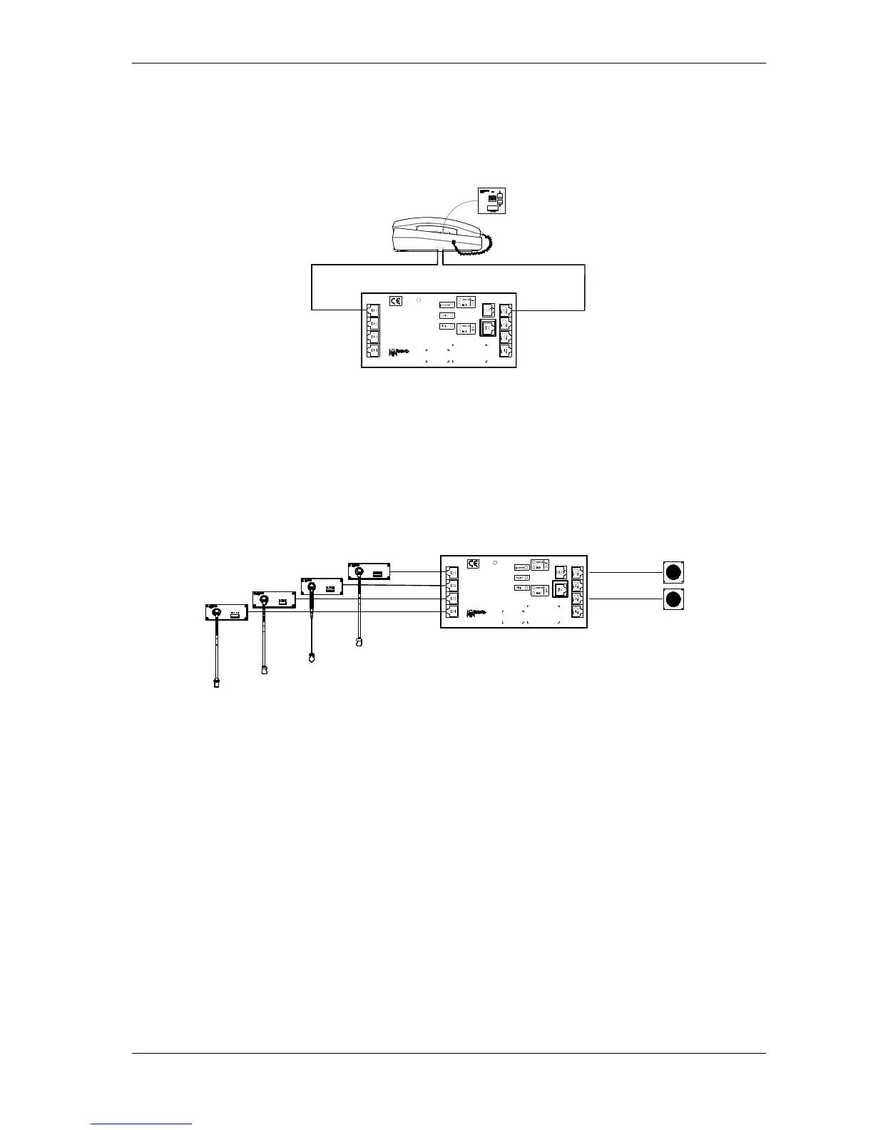
1 IHS5500
You can connect up to four IHS5500 units to the INT5500. An IHS
system uses one MIC port and one DCS port with the same
number.
Special configurations
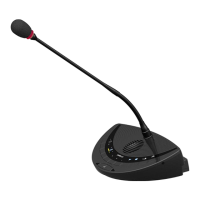
2 Microphones – 1 loudspeaker
In this configuration there is only one loudspeaker (LS5500) for
two microphones. One loudspeaker is connected to port 1 and the
other to port 3.
When so configured in the operational control suite software, the
microphones connected to MIC port 1 and 2 of the INT5500 will
mute the LS5500 connected to DCS port 1 of the INT5500 when
one of the two microphones is activated. The same is true for the
microphones connected to MIC ports 3 and 4. If they are activated
the LS5500 connected to DCS port 3 will be muted.
Master – slave microphones
Two microphone panels can share 1 physical microphone. The
following must be taken into account
The master microphone panel must be connected to port number 1
or 3 of the INT5500. This microphone panel must contain the
shared microphone and audio path.