15
14
13
12
11
10 9 8
7
6
5
4
3
2
1
0
+
+
+
in_bit
M0105-01
Introduction
www.ti.com
14.1 Introduction
The random-number generator has the following features.
• Generates pseudorandom bytes which can be read by the CPU or used directly by the command
strobe processor (see Section 23.14).
• Calculates CRC16 of bytes that are written to RNDH.
• Seeded by value written to RNDL.
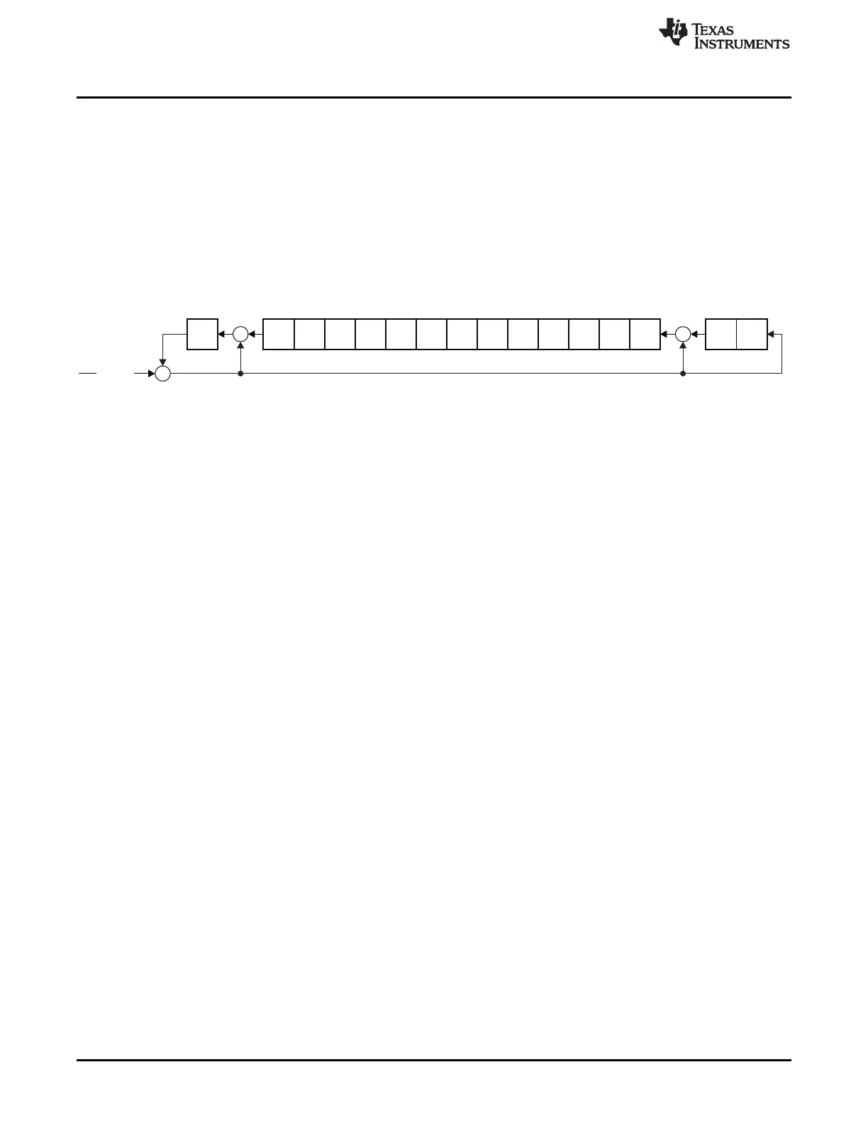
The random-number generator is a 16-bit linear-feedback shift register (LFSR) with polynomial X
16
+ X
15
+
X
2
+ 1 (i.e., CRC16). It uses different levels of unrolling depending on the operation it performs. The basic
version (no unrolling) is shown in Figure 14-1.
The random-number generator is turned off when ADCCON1.RCTRL = 11.
Figure 14-1. Basic Structure of the Random-Number Generator
14.2 Random-Number-Generator Operation
The operation of the random-number generator is controlled by the ADCCON1.RCTRL bits (see also
Section 12.2.10). The current value of the 16-bit shift register in the LFSR can be read from the RNDH and
RNDL registers.
14.2.1 Pseudorandom Sequence Generation
The default operation (ADCCON1.RCTRL is 00) is to clock the LFSR once (13× unrolling; where clocking
with 13× unrolling means performing an operation equivalent to doing 13 shifts with feedback) each time
the command strobe processor (Section 23.14) reads the random value. This leads to the availability of a
fresh pseudorandom byte from the LSB end of the LFSR.
Another way to update the LFSR is to set ADCCON1.RCTRL to 01. This clocks the LFSR once (13×
unrolling), and the ADCCON1.RCTRL bits are automatically cleared when the operation has completed.
14.2.2 Seeding
The LFSR can be seeded by writing to the RNDL register twice. Each time the RNDL register is written, the
8 LSBs of the LFSR are copied to the 8 MSBs and the 8 LSBs are replaced with the new data byte that
was written to RNDL.
For the CC253x, when a random value is required, the LFSR should be seeded by writing RNDL with
random bits from the IF_ADC in the RF receive path. To use this seeding method, the radio must first be
powered on. The radio should be placed in the infinite RX state to avoid possible sync detect in the RX
state. The random bits from the IF_ADC are read from the least significant bit position of the RF register
RFRND. These bits should be concatenated over time to form the bytes needed for the
random-number-generator seed. See Section 23.12 for a description of the randomness of these
numbers. Note that this cannot be done while the radio is in use for normal tasks.
Note that a seed value of 0x0000 or 0x8003 always leads to an unchanged value in the LFSR after
clocking, as no values are pushed in via in_bit (see Figure 14-1); hence, neither of these seed values
should not be used for random-number generation.
14.2.3 CRC16
The LFSR can also be used to calculate the CRC value of a sequence of bytes. Writing to the RNDH
register triggers a CRC calculation. The new byte is processed from the MSB end and an 8× unrolling is
used, so that a new byte can be written to RNDH every clock cycle.
150
Random-Number Generator SWRU191C–April 2009–Revised January 2012
Submit Documentation Feedback
Copyright © 2009–2012, Texas Instruments Incorporated
 Loading...


