Instruction Set Summary
www.ti.com
The instructions that affect CPU flag settings located in PSW are listed in Table 2-4. Note that operations
on the PSW register or bits in PSW also affect the flag settings. Also note that the cycle count for many
instructions assumes single-cycle access to the memory element being accessed, i.e., the best-case
situation. This is not always the case. Reads from flash may take 1–3 cycles, for example.
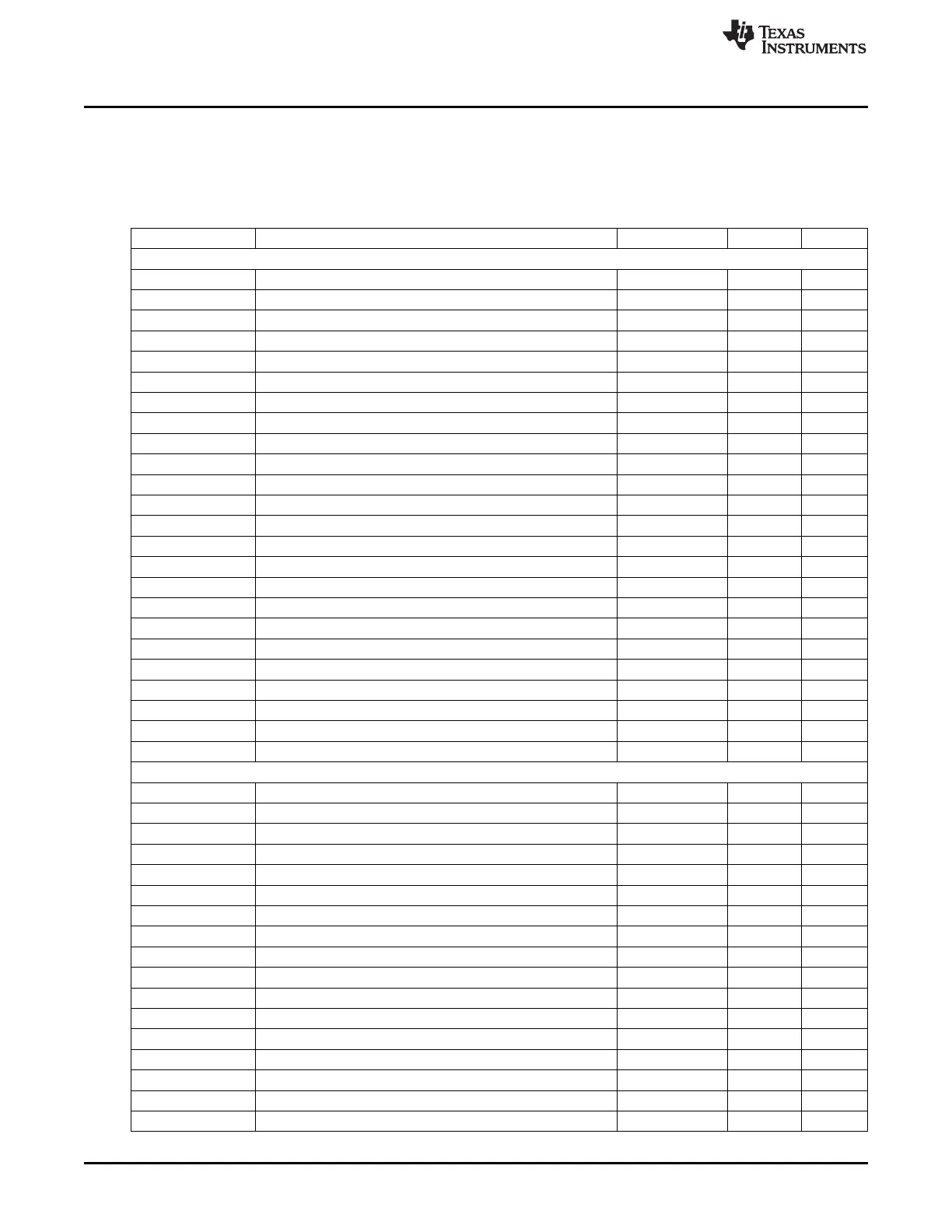
Table 2-3. Instruction Set Summary
Mnemonic Description Hex Opcode Bytes Cycles
ARITHMETIC OPERATIONS
ADD A,Rn Add register to accumulator 28–2F 1 1
ADD A,direct Add direct byte to accumulator 25 2 2
ADD A,@Ri Add indirect RAM to accumulator 26–27 1 2
ADD A,#data Add immediate data to accumulator 24 2 2
ADDC A,Rn Add register to accumulator with carry flag 38–3F 1 1
ADDC A,direct Add direct byte to A with carry flag 35 2 2
ADDC A,@Ri Add indirect RAM to A with carry flag 36–37 1 2
ADDC A,#data Add immediate data to A with carry flag 34 2 2
SUBB A,Rn Subtract register from A with borrow 98–9F 1 1
SUBB A,direct Subtract direct byte from A with borrow 95 2 2
SUBB A,@Ri Subtract indirect RAM from A with borrow 96–97 1 2
SUBB A,#data Subtract immediate data from A with borrow 94 2 2
INC A Increment accumulator 04 1 1
INC Rn Increment register 08–0F 1 2
INC direct Increment direct byte 05 2 3
INC @Ri Increment indirect RAM 06–07 1 3
INC DPTR Increment data pointer A3 1 1
DEC A Decrement accumulator 14 1 1
DEC Rn Decrement register 18–1F 1 2
DEC direct Decrement direct byte 15 2 3
DEC @Ri Decrement indirect RAM 16–17 1 3
MUL AB Multiply A and B A4 1 5
DIV A Divide A by B 84 1 5
DA A Decimal adjust accumulator D4 1 1
LOGICAL OPERATIONS
ANL A,Rn AND register to accumulator 58–5F 1 1
ANL A,direct AND direct byte to accumulator 55 2 2
ANL A,@Ri AND indirect RAM to accumulator 56–57 1 2
ANL A,#data AND immediate data to accumulator 54 2 2
ANL direct,A AND accumulator to direct byte 52 2 3
ANL direct,#data AND immediate data to direct byte 53 3 4
ORL A,Rn OR register to accumulator 48–4F 1 1
ORL A,direct OR direct byte to accumulator 45 2 2
ORL A,@Ri OR indirect RAM to accumulator 46–47 1 2
ORL A,#data OR immediate data to accumulator 44 2 2
ORL direct,A OR accumulator to direct byte 42 2 3
ORL direct,#data OR immediate data to direct byte 43 3 4
XRL A,Rn Exclusive OR register to accumulator 68–6F 1 1
XRL A,direct Exclusive OR direct byte to accumulator 65 2 2
XRL A,@Ri Exclusive OR indirect RAM to accumulator 66–67 1 2
XRL A,#data Exclusive OR immediate data to accumulator 64 2 2
XRL direct,A Exclusive OR accumulator to direct byte 62 2 3
40
8051 CPU SWRU191C–April 2009–Revised January 2012
Submit Documentation Feedback
Copyright © 2009–2012, Texas Instruments Incorporated
 Loading...


