www.ti.com
Debug Commands
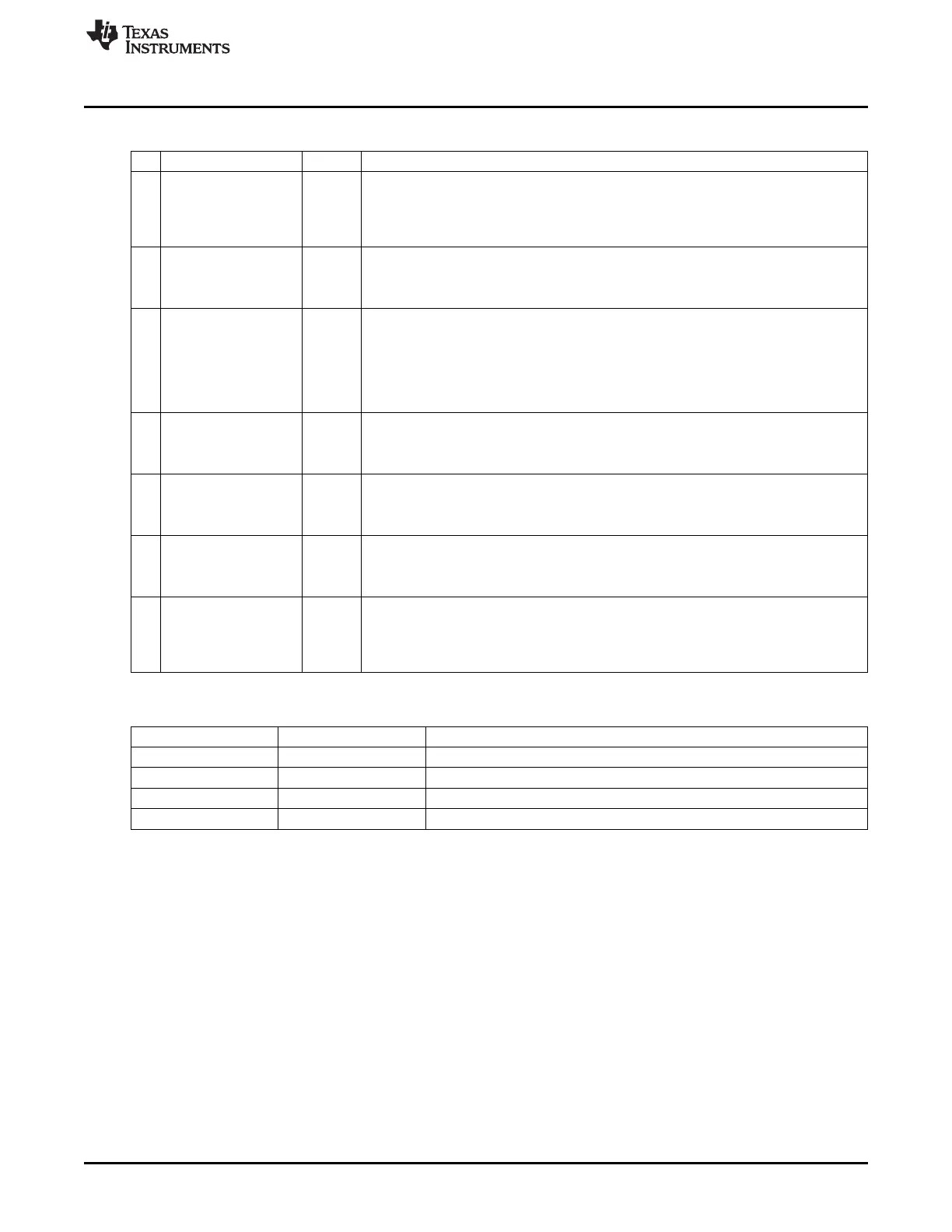
Table 3-3. Debug Status (continued)
Bit Name Reset Description
6
PCON_IDLE
0 PCON idle. See also Table 3-4.
0: CPU is running. Chip in operational mode controlled by debugger.
1:
CPU is not running. Chip is in power mode defined by SLEEPCMD.MODE register
setting. See Section 4.1 - Section 4.3 for details.
5
CPU_HALTED
0 CPU was halted
0: CPU is running.
1: CPU was halted from a breakpoint or from a HALT debug command.
4
PM_ACTIVE
0 Chip is active. Note that PM0 and PM1 are not supported in debug mode. See also
Table 3-4.
0: Chip is in normal operation with CPU running (if not halted).
1: Chip is out of normal operation (active mode) and either in transition up or down from
power mode or stable in the power mode defined by SLEEPCMD.MODE register
setting. See Section 4.1 - Section 4.3 for details.
3
HALT_STATUS
0 Halt status. Returns cause of last CPU halt
0: CPU was halted by HALT debug command
1: CPU was halted by hardware breakpoint
2
DEBUG_LOCKED
0
Debug interface is locked. Returns value of DBGLOCK bit. See Section 3.4.1.
0: Debug interface is not locked.
1: Debug interface is locked.
1
OSCILLATOR_STABLE
0 System clock oscillator stable.
0: Oscillators not stable
1: Oscillators stable
0
STACK_OVERFLOW
0 Stack overflow. This bit indicates when the CPU writes to DATA memory space at
address 0xFF, which is possibly a stack overflow.
0: No stack overflow
1: Stack overflow
Table 3-4. Relation Between PCON_IDLE and PM_ACTIVE
PCON_IDLE PM_ACTIVE
Description
0 0 Chip in normal operation with CPU running (if not halted)
0 1 Chip in transition to start-up from power mode
1 0 Chip in transition to enter power mode
1 1 Chip stable in power mode
3.3.3 Hardware Breakpoints
The debug command SET_HW_BRKPNT is used to set one of the four available hardware breakpoints.
When a hardware breakpoint is enabled, it compares the CPU address bus with the breakpoint. When a
match occurs, the CPU is halted.
When issuing the SET_HW_BRKPNT, the external host must supply three data bytes that define the
hardware breakpoint. The hardware breakpoint itself consists of 19 bits, whereas three bits are used for
control purposes. The format of the three data bytes for the SET_HW_BRKPNT command is as follows.
The first data byte consists of the following:
• Bits 7–6: Unused
• Bits 5–4: Breakpoint number, 0–3
• Bit 3: 1 = enable, 0 = disable
• Bits 2–0: Memory bank bits. Bits 18–16 of hardware breakpoint.
The second data byte consists of bits 15–8 of the hardware breakpoint.
59
SWRU191C–April 2009–Revised January 2012 Debug Interface
Submit Documentation Feedback
Copyright © 2009–2012, Texas Instruments Incorporated
 Loading...


