Flash Controller Registers
www.ti.com
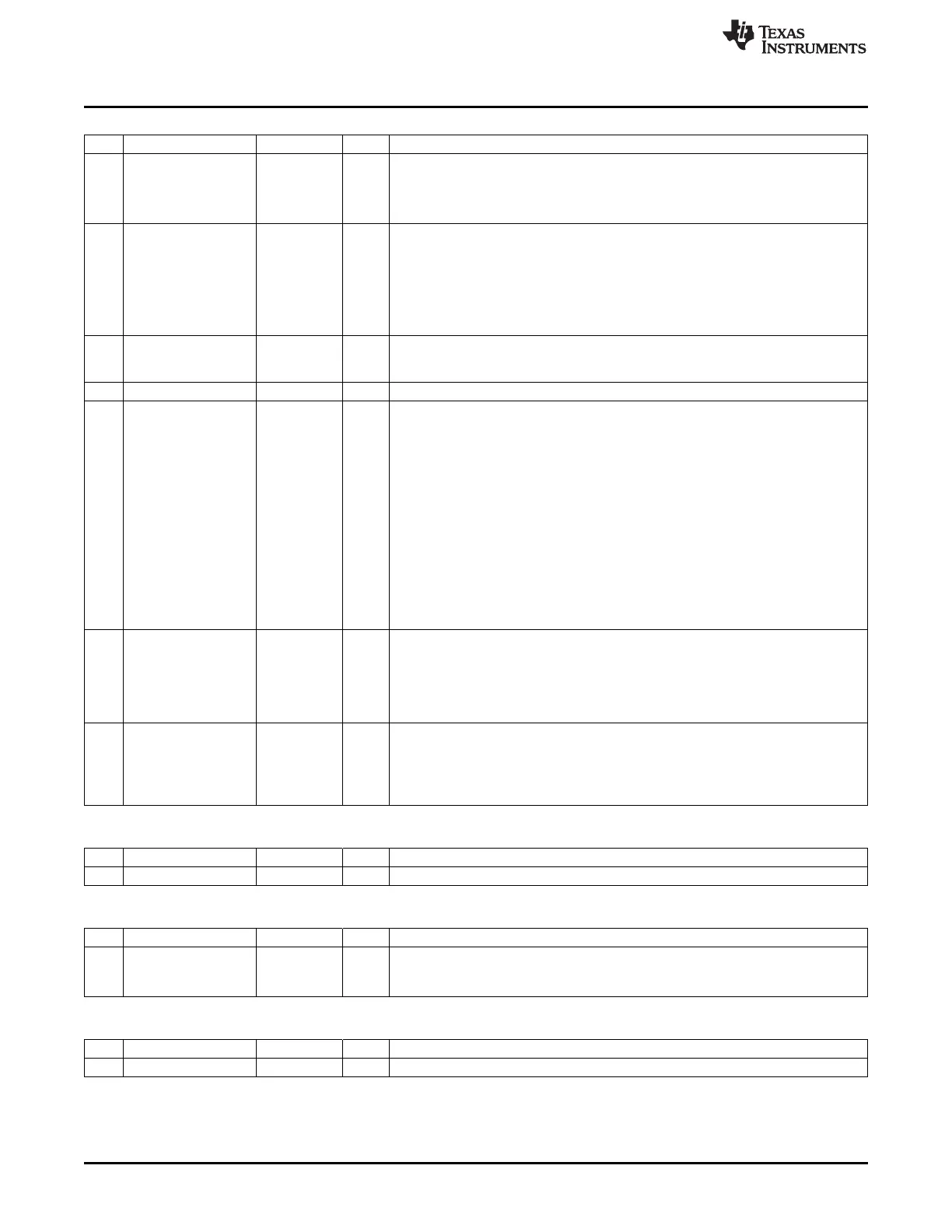
FCTL (0x6270) – Flash Control
Bit Name Reset R/W Description
7
BUSY
0 R Indicates that write or erase is in operation. This flag is set when the WRITE or
ERASE bit is set.
0: No write or erase operation active
1: Write or erase operation activated
6
FULL
R/H0
Write buffer-full status. This flag is set when 4 bytes have been written to FWDATA
during flash write. The write buffer is then full and does not accept more data; i.e,
writes to FWDATA are ignored when the FULL flag is set. The FULL flag is cleared
when the write buffer again is ready to receive 4 more bytes. This flag is only
needed when the CPU is used to write to the flash.
0: Write buffer can accept more data.
1: Write buffer full
5
ABORT
0 R/H0 Abort status. This bit is set when a write operation or page erase is aborted. An
operation is aborted when the page accessed is locked. The abort bit is cleared
when a write or page erase is started.
4 – 0 R Reserved
3:2
CM[1:0]
01 R/W Cache mode
00: Cache disabled
01: Cache enabled
10: Cache enabled, prefetch mode
11: Cache enabled, real-time mode
Cache mode. Disabling the cache increases the power consumption and reduces
performance. Prefetching, for most applications, improves performance by up to
33% at the expense of potentially increased power consumption. Real-time mode
provides predictable flash-read access time; the execution time is equal to that in
cache-disabled mode, but the power consumption is lower.
Note: The value read always represents the current cache mode. Writing a new
cache mode starts a cache mode-change request that may take several clock cycles
to complete. Writing to this register is ignored if there is a current cache-change
request in progress.
1
WRITE
0 R/W1/
Write. Start writing word at location given by FADDRH:FADDRL. The WRITE bit stays
H0 at 1 until the write completes. The clearing of this bit indicates that the erase has
completed, i.e., it has timed out or aborted.
If ERASE is also set to 1, a page erase of the whole page addressed by
FADDRH[7:1] is performed before the write. Setting WRITE to 1 when ERASE is 1
has no effect.
0
ERASE
0 R/W1/
Page erase. Erase the page that is given by FADDRH[7:1]
H0
(CC2530/CC2531/CC2540/CC2541) or FADDRH[6:0] (CC2533) . The ERASE
bit stays at 1 until the erase completes. The clearing of this bit indicates that the
erase has completed successfully or aborted.
Setting ERASE to 1 when WRITE is 1 has no effect.
FWDATA (0x6273) – Flash Write Data
Bit Name Reset R/W Description
7:0
FWDATA[7:0]
0x00 R0/W
Flash write data. This register can only be written to when FCTL.WRITE is 1.
FADDRH (0x6272) – Flash-Address High Byte
Bit Name Reset R/W Description
7:0
FADDRH[7:0]
0x00 R/W Page address/high byte of flash word address
Bits [7:1] (CC2530/CC2531/CC2540/CC2541) or bits [6:0] (CC2533) select
which page to access.
FADDRL (0x6271) – Flash-Address Low Byte
Bit Name Reset R/W Description
7:0
FADDRL[7:0]
0x00 R/W Low byte of flash word address
80
Flash Controller SWRU191C– April 2009–Revised January 2012
Submit Documentation Feedback
Copyright © 2009–2012, Texas Instruments Incorporated
 Loading...


