www.ti.com
USB Registers
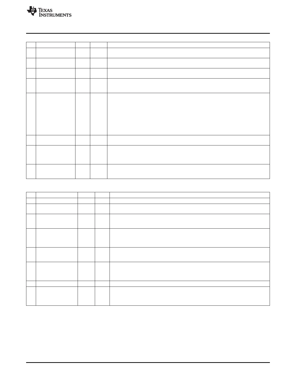
USBCS0 (0x6211) – EP0 Control and Status (USBINDEX = 0)
Bit Name Reset R/W Description
7
CLR_SETUP_END
0 R/W H0
Set this bit to 1 to de-assert the SETUP_END bit of this register. This bit is cleared
automatically.
6
CLR_OUTPKT_RDY
0 R/W H0
Set this bit to 1 to de-assert the OUTPKT_RDY bit of this register. This bit is cleared
automatically.
5
SEND_STALL
0 R/W H0 Set this bit to 1 to terminate the current transaction. The USB controller sends the STALL
handshake and this bit is de-asserted.
4
SETUP_END
0 R This bit is set if the control transfer ends due to a premature end-of-control transfer. The
FIFO is flushed and an interrupt request (EP0) is generated if the interrupt is enabled.
Setting CLR_SETUP_END = 1 de-asserts this bit.
3
DATA_END
0 R/W H0 This bit is used to signal the end of a data transfer and must be asserted in the following
three situations:
1:
When the last data packet has been loaded and USBCS0.INPKT_RDY is set to 1
2:
When the last data packet has been unloaded and USBCS0.CLR_OUTPKT_RDY is set
to 1
3:
When USBCS0.INPKT_RDY has been asserted without having loaded the FIFO (for
sending a zero-length data packet).
The USB controller clears this bit automatically.
2
SENT_STALL
0 R/W H1 This bit is set when a STALL handshake has been sent. An interrupt request (EP0) is
generated if the interrupt is enabled. This bit must be cleared from firmware.
1
INPKT_RDY
0 R/W H0 Set this bit when a data packet has been loaded into the EP0 FIFO to notify the USB
controller that a new data packet is ready to be transferred. When the data packet has been
sent, this bit is cleared, and an interrupt request (EP0) is generated if the interrupt is
enabled.
0
OUTPKT_RDY
0 R Data packet received. This bit is set when an incoming data packet has been placed in the
OUT FIFO. An interrupt request (EP0) is generated if the interrupt is enabled. Set
CLR_OUTPKT_RDY = 1 to de-assert this bit.
USBCSIL (0x6211) – IN EP{1–5} Control and Status, Low
Bit Name Reset R/W Description
7 – – R0 Reserved
6
CLR_DATA_TOG
0 R/W Setting this bit resets the data toggle to 0. Thus, setting this bit forces the next data packet
H0 to be a DATA0 packet. This bit is automatically cleared.
5
SENT_STALL
0 R/W This bit is set when a STALL handshake has been sent. The FIFO is flushed and the
INPKT_RDY bit in this register is de-asserted. An interrupt request (IN EP{1–5}) is
generated if the interrupt is enabled. This bit must be cleared from firmware.
4
SEND_STALL
0 R/W Set this bit to 1 to make the USB controller reply with a STALL handshake when receiving
IN tokens. Firmware must clear this bit to end the STALL condition. It is not possible to stall
an isochronous endpoint; thus, this bit only has an effect if the IN endpoint is configured as
bulk/interrupt.
3
FLUSH_PACKET
0 R/W
Set to 1 to flush next packet that is ready to transfer from the IN FIFO. The INPKT_RDY bit
H0 in this register is cleared. If there are two packets in the IN FIFO due to double buffering,
this bit must be set twice to completely flush the IN FIFO. This bit is automatically cleared.
2
UNDERRUN
0 R/W In isochronous mode, this bit is set if an IN token is received when
INPKT_RDY = 0, and a zero-length data packet is transmitted in response to the
IN token. In bulk/interrupt mode, this bit is set when a NAK is returned in response to an IN
token. Firmware should clear this bit.
1
PKT_PRESENT
0 R This bit is 1 when there is at least one packet in the IN FIFO.
0
INPKT_RDY
0 R/W Set this bit when a data packet has been loaded into the IN FIFO to notify the USB
H0 controller that a new data packet is ready to be transferred. When the data packet has
been sent, this bit is cleared, and an interrupt request (IN EP{1–5}) is generated if the
interrupt is enabled.
203
SWRU191C–April 2009–Revised January 2012 USB Controller
Submit Documentation Feedback
Copyright © 2009–2012, Texas Instruments Incorporated
 Loading...


