CPU Registers
www.ti.com
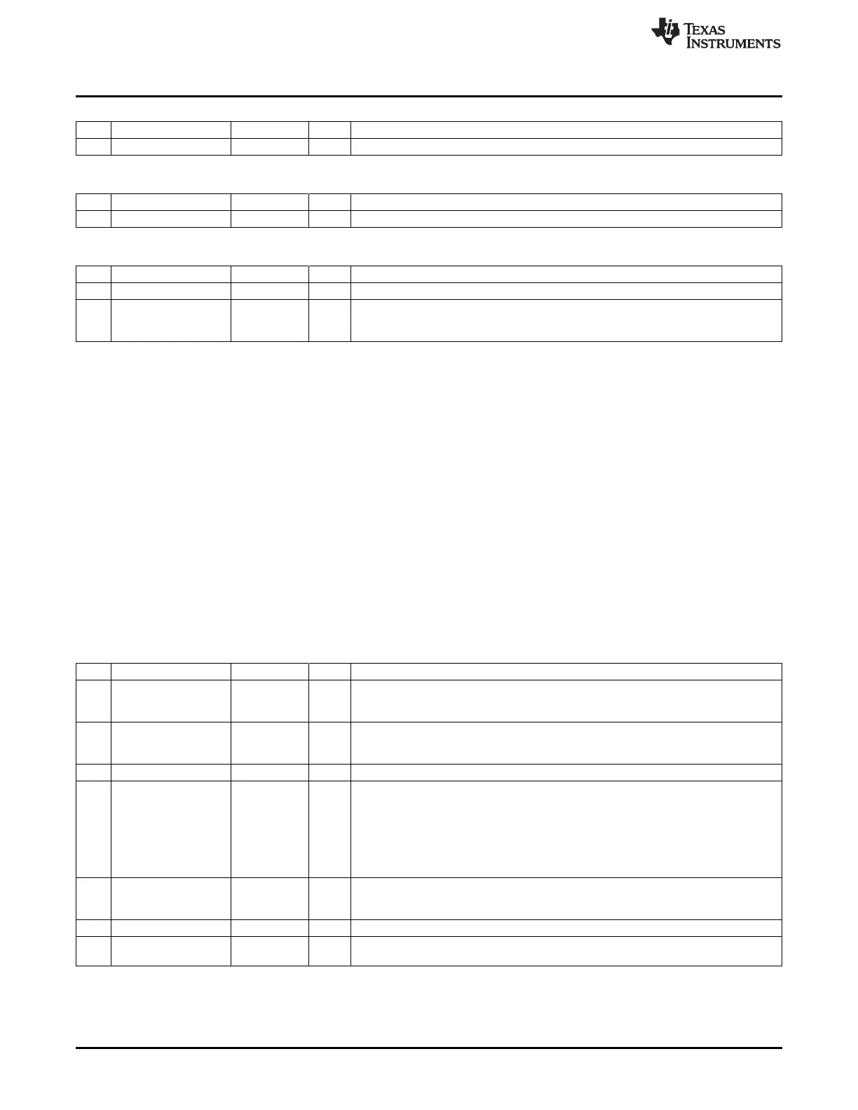
DPH1 (0x85) – Data Pointer-1 High Byte
Bit Name Reset R/W Description
7:0
DPH1[7:0]
0x00 R/W Data pointer-1, high byte
DPL1 (0x84) – Data Pointer-1 Low Byte
Bit Name Reset R/W Description
7:0
DPL1[7:0]
0x00 R/W Data pointer-1, low byte
DPS (0x92) – Data-Pointer Select
Bit Name Reset R/W Description
7:1 – 0000 000 R0 Reserved
0
DPS
0 R/W Data pointer select. Selects active data pointer.
0: DPTR0
1: DPTR1
2.3.2 Registers R0–R7
There are four register banks (not to be confused with CODE memory space banks that only apply to flash
memory organization) of eight registers each. These register banks are mapped in the DATA memory
space at addresses 0x00–0x07, 0x08–0x0F, 0x10–0x17, and 0x18–0x1F. Each register bank contains the
eight 8-bit registers R0–R7. The register bank to be used is selected through the program status word
PSW.RS[1:0]. Register bank 0 uses flip-flops internally for storing the values (SRAM is
bypassed/unused), whereas banks 1–3 use SRAM for storage. This is done to save power. Typically, the
current consumption goes down by approximately 200 μA by using register bank 0 instead of register
banks 1–3.
2.3.3 Program Status Word
The program status word (PSW) contains several bits that show the current state of the CPU. The PSW is
accessible as an SFR, and it is bit-addressable. The PSW is shown as follows and contains the carry flag,
auxiliary carry flag for BCD operations, register-select bits, overflow flag, and parity flag. Two bits in the
PSW are uncommitted and can be used as user-defined status flags.
PSW (0xD0) – Program Status Word
Bit Name Reset R/W Description
7
CY
0 R/W Carry flag. Set to 1 when the last arithmetic operation resulted in a carry (during
addition) or borrow (during subtraction); otherwise, cleared to 0 by all arithmetic
operations.
6
AC
0 R/W Auxiliary carry flag for BCD operations. Set to 1 when the last arithmetic operation
resulted in a carry into (during addition) or borrow from (during subtraction) the
high-order nibble, otherwise cleared to 0 by all arithmetic operations.
5
F0
0 R/W User-defined, bit-addressable
4:3
RS[1:0]
00 R/W Register bank select bits. Selects which set of R7–R0 registers to use from four
possible banks in DATA space.
00: Register bank 0, 0x00–0x07
01: Register bank 1, 0x08–0x0F
10: Register bank 2, 0x10–0x17
11: Register bank 3, 0x18–0x1F
2
OV
0 R/W Overflow flag, set by arithmetic operations. Set to 1 when the last arithmetic
operation is a carry (addition), borrow (subtraction), or overflow (multiply or divide).
Otherwise, the bit is cleared to 0 by all arithmetic operations.
1
F1
0 R/W User-defined, bit-addressable
0
P
0 R/W Parity flag, parity of accumulator set by hardware to 1 if it contains an odd number of
1s; otherwise it is cleared to 0.
38
8051 CPU SWRU191C–April 2009–Revised January 2012
Submit Documentation Feedback
Copyright © 2009–2012, Texas Instruments Incorporated
 Loading...


