LMK04821
,
LMK04826
,
LMK04828
SNAS605AR –MARCH 2013–REVISED DECEMBER 2015
www.ti.com
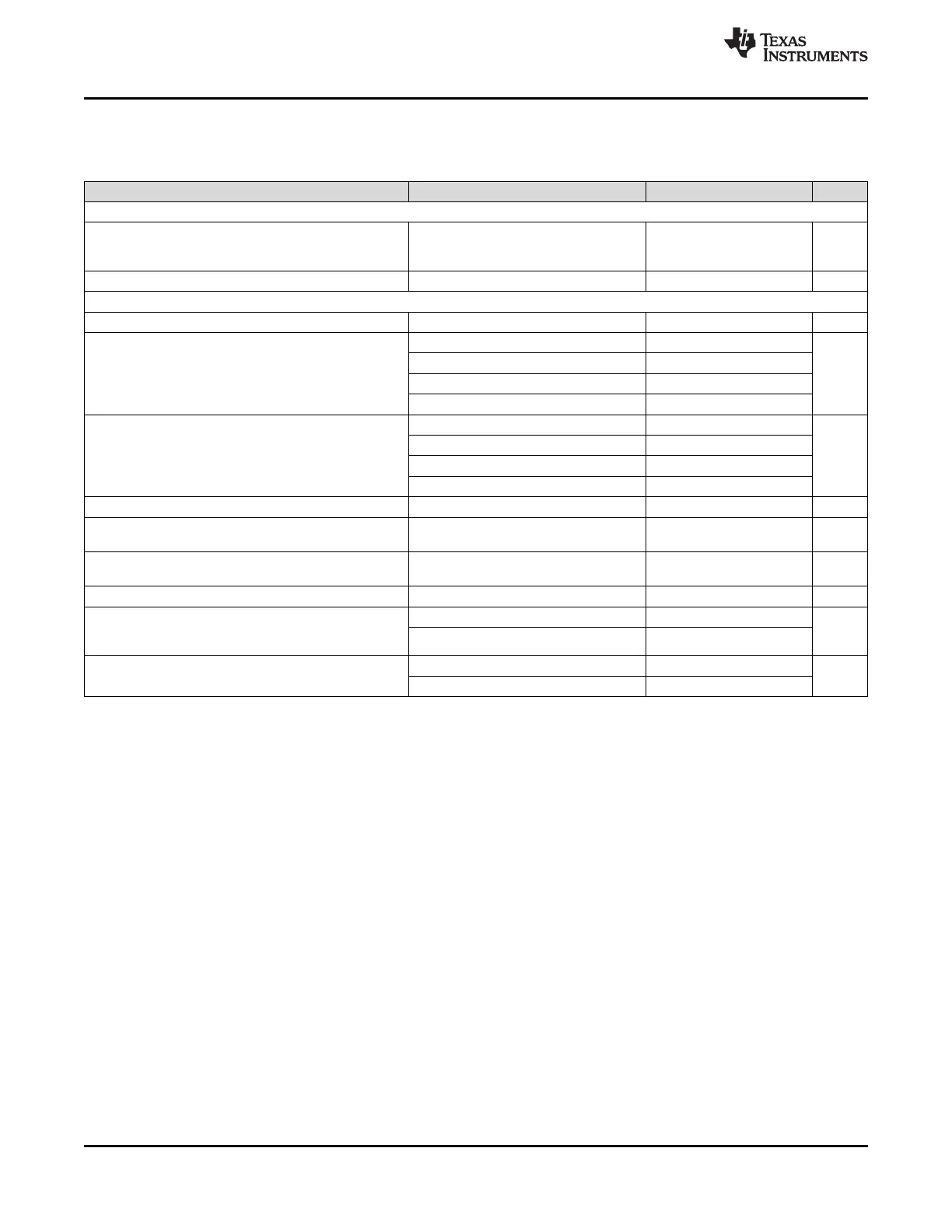
Electrical Characteristics (continued)
(3.15 V < V
CC
< 3.45 V, –40 °C < T
A
< 85 °C and T
PCB
≤ 105 °C. Typical values at V
CC
= 3.3 V, T
A
= 25 °C, at the
Recommended Operating Conditions and are not assured.)
PARAMETER TEST CONDITIONS MIN TYP MAX UNIT
CRYSTAL OSCILLATOR MODE SPECIFICATIONS
Fundamental mode crystal
F
XTAL
Crystal Frequency Range ESR = 200 Ω (10 to 30 MHz) 10 40 MHz
ESR = 125 Ω (30 to 40 MHz)
C
IN
Input Capacitance of OSCin port –40 to 85 °C 1 pF
PLL2 PHASE DETECTOR and CHARGE PUMP SPECIFICATIONS
f
PD2
Phase Detector Frequency
(7)
155 MHz
V
CPout2
=V
CC
/2, PLL2_CP_GAIN = 0 100
V
CPout2
=V
CC
/2, PLL2_CP_GAIN = 1 400
PLL2 Charge Pump Source Current
I
CPout
SOURCE µA
(5)
V
CPout2
=V
CC
/2, PLL2_CP_GAIN = 2 1600
V
CPout2
=V
CC
/2, PLL2_CP_GAIN = 3 3200
V
CPout2
=V
CC
/2, PLL2_CP_GAIN = 0 –100
V
CPout2
=V
CC
/2, PLL2_CP_GAIN = 1 –400
I
CPout
SINK PLL2 Charge Pump Sink Current
(5)
µA
V
CPout2
=V
CC
/2, PLL2_CP_GAIN = 2 –1600
V
CPout2
=V
CC
/2, PLL2_CP_GAIN = 3 –3200
I
CPout2
%MIS Charge Pump Sink/Source Mismatch V
CPout2
=V
CC
/2, T
A
= 25 °C 1% 10%
Magnitude of Charge Pump Current 0.5 V < V
CPout2
< V
CC
- 0.5 V
I
CPout2
V
TUNE
4%
vs. Charge Pump Voltage Variation T
A
= 25 °C
Charge Pump Current vs.
I
CPout2
%TEMP 4%
Temperature Variation
I
CPout2
TRI Charge Pump Leakage 0.5 V < V
CPout2
< V
CC
- 0.5 V 10 nA
PLL 1/f Noise at 10 kHz offset
(9)
. PLL2_CP_GAIN = 400 µA –118
PN10kHz Normalized to dBc/Hz
PLL2_CP_GAIN = 3200 µA –121
1 GHz Output Frequency
PLL2_CP_GAIN = 400 µA –222.5
Normalized Phase Noise Contribution
PN1Hz dBc/Hz
(10)
PLL2_CP_GAIN = 3200 µA –227
(9) A specification in modeling PLL in-band phase noise is the 1/f flicker noise, L
PLL_flicker
(f), which is dominant close to the carrier. Flicker
noise has a 10 dB/decade slope. PN10kHz is normalized to a 10 kHz offset and a 1 GHz carrier frequency. PN10kHz = L
PLL_flicker
(10
kHz) - 20log(Fout / 1 GHz), where L
PLL_flicker
(f) is the single side band phase noise of only the flicker noise's contribution to total noise,
L(f). To measure L
PLL_flicker
(f) it is important to be on the 10 dB/decade slope close to the carrier. A high compare frequency and a clean
crystal are important to isolating this noise source from the total phase noise, L(f). L
PLL_flicker
(f) can be masked by the reference
oscillator performance if a low power or noisy source is used. The total PLL in-band phase noise performance is the sum of L
PLL_flicker
(f)
and L
PLL_flat
(f).
(10) A specification modeling PLL in-band phase noise. The normalized phase noise contribution of the PLL, L
PLL_flat
(f), is defined as:
PN1HZ=L
PLL_flat
(f) - 20log(N) - 10log(f
PDX
). L
PLL_flat
(f) is the single side band phase noise measured at an offset frequency, f, in a 1 Hz
bandwidth and f
PDX
is the phase detector frequency of the synthesizer. L
PLL_flat
(f) contributes to the total noise, L(f).
12 Submit Documentation Feedback Copyright © 2013–2015, Texas Instruments Incorporated
Product Folder Links: LMK04821 LMK04826 LMK04828