20
TMS570LS0714
SPNS226E –JUNE 2013–REVISED NOVEMBER 2016
www.ti.com
Submit Documentation Feedback
Product Folder Links: TMS570LS0714
Terminal Configuration and Functions Copyright © 2013–2016, Texas Instruments Incorporated
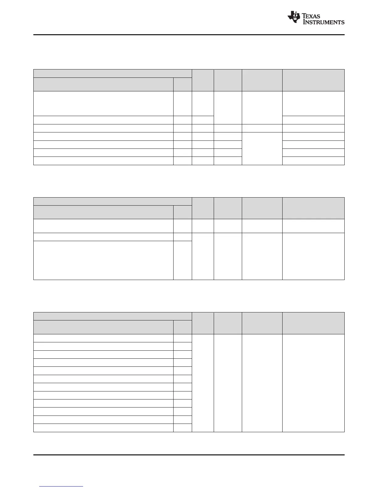
4.2.1.15 Test and Debug Modules Interface
Table 4-15. PGE Test and Debug Modules Interface
Terminal Signal
Type
Reset Pull
State
Pull Type Description
Signal Name 144
PGE
TEST 34 Input Pulldown Fixed, 100 µA Test enable. This terminal
must be connected to
ground directly or via a
pulldown resistor.
nTRST 109 Input JTAG test hardware reset
RTCK 113 Output - None JTAG return test clock
TCK 112 Input Pulldown Fixed, 100 µA JTAG test clock
TDI 110 Input Pullup JTAG test data in
TDO 111 Output Pulldown JTAG test data out
TMS 108 Input Pullup JTAG test select
4.2.1.16 Flash Supply and Test Pads
Table 4-16. PGE Flash Supply and Test Pads
Terminal Signal
Type
Reset Pull
State
Pull Type Description
Signal Name 144
PGE
VCCP 134 3.3-V
Power
– None Flash pump supply
FLTP1 7 – – None Flash test pads. These
terminals are reserved for
TI use only. For proper
operation these terminals
must connect only to a
test pad or not be
connected at all [no
connect (NC)].
FLTP2 8
4.2.1.17 Supply for Core Logic: 1.2V nominal
Table 4-17. PGE Supply for Core Logic: 1.2V nominal
Terminal Signal
Type
Reset Pull
State
Pull Type Description
Signal Name 144
PGE
VCC 17 1.2-V
Power
– None Core supply
VCC 29
VCC 45
VCC 48
VCC 49
VCC 57
VCC 87
VCC 101
VCC 114
VCC 123
VCC 137
VCC 143
 Loading...


