Copyright © 2013–2016, Texas Instruments Incorporated Terminal Configuration and Functions
Submit Documentation Feedback
Product Folder Links: TMS570LS0714
31
TMS570LS0714
www.ti.com
SPNS226E –JUNE 2013–REVISED NOVEMBER 2016
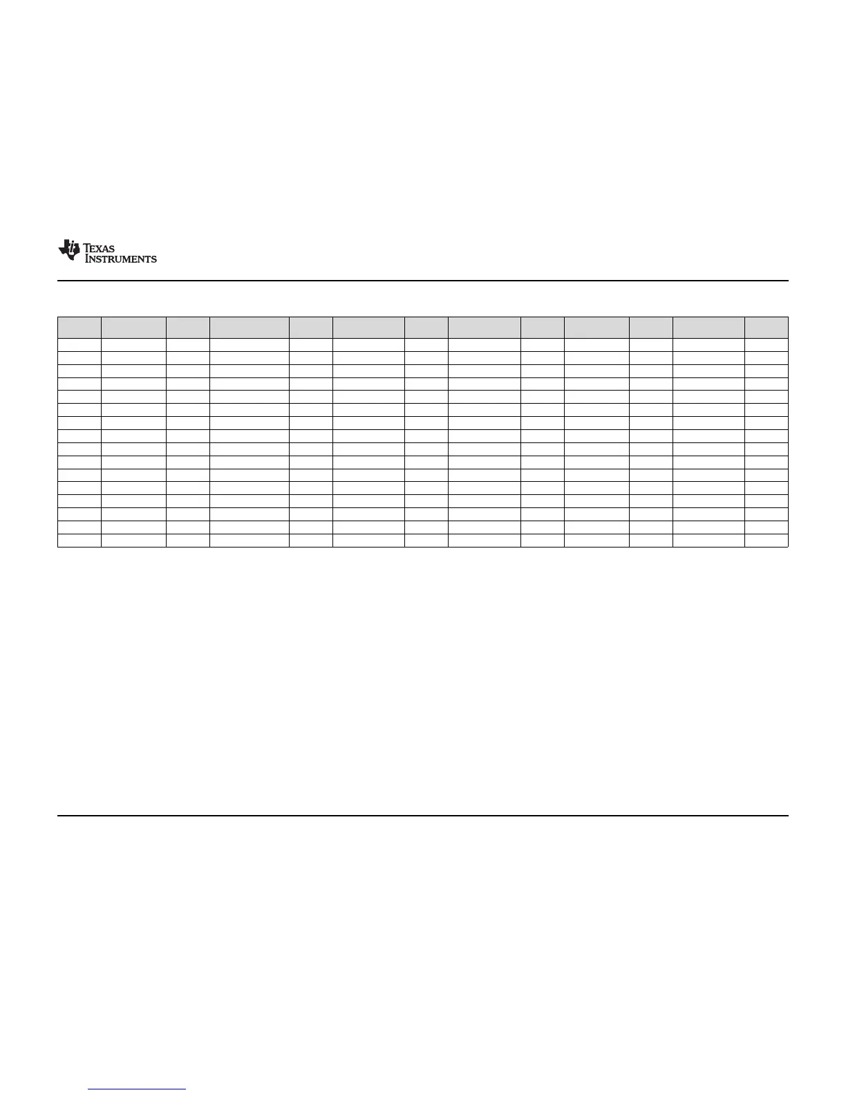
Table 4-37. Multiplexing for Outputs on 144-Pin PGE Package(1) (continued)
144-PIN
PGE
DEFAULT
FUNCTION
CTRL1 OPTION 2 CTRL2 OPTION 3 CTRL3 OPTION 4 CTRL4 OPTION 5 CTRL5 OPTION 6 CTRL6
106 N2HET1[08] 14[0] MIBSPI1SIMO[1] 14[1]
35 N2HET1[09] 6[16] N2HET2[16] 6[17] EPWM7A 6[20]
118 N2HET1[10] 17[0] nTZ3 17[4]
6 N2HET1[11] 1[8] MIBSPI3NCS[4] 1[9] N2HET2[18] 1[10] EPWM1SYNCO 1[13]
124 N2HET1[12] 17[16]
39 N2HET1[13] 8[0] SCITX 8[1] EPWM5B 8[2]
125 N2HET1[14] 18[8]
41 N2HET1[15] 8[16] MIBSPI1NCS[4] 8[17] ECAP1 8[18]
139 N2HET1[16] 34[0] EPWM1SYNCI 34[1] EPWM1SYNCO 34[2]
140 N2HET1[18] 34[8] EPWM6A 34[9]
141 N2HET1[20] 34[16] EPWM6B 34[17]
15 N2HET1[22] 3[8]
91 N2HET1[24] 11[24] MIBSPI1NCS[5] 11[25]
92 N2HET1[26] 12[0]
107 N2HET1[28] 14[8]
127 N2HET1[30] 19[8] EQEP2S 19[11]
(1) The CTRLx columns contain a value of type x[y], which indicates the pin multiplexing control x register (PINMMRx) and the associated bit field [y].
 Loading...


