GCLK, GCLK2 (to CPU)
GCM
HCLK (to SYSTEM)
VCLK_peri (VCLK to peripherals on PCR1)
RTICLK (to RTI, DWWD)
/1, 2, 4, or 8
VCLK
OSCIN
Low-Power
Oscillator
10 MHz
80 kHz
1
0
4
5
/1..64
X1..256
/1..8
/1..32
6
*
VCLK
/1,2,..1024
Phase_seg2
CAN Baud Rate
Phase_seg1
VCLKA1
/1,2,..256
SPIx,MibSPIx
/2,3..2
24
LIN, SCI
SPI
LIN / SCI
/1,2..32
MibADCx
ADCLK
/1,2..65536
External Clock
ECLK
VCLK2
N2HETx
HRP
/1..64
LRP
/2
0
..2
5
Loop
Resolution Clock
High
Baud Rate
Baud Rate
N2HETx
TU
VCLK2
EXTCLKIN1
EXTCLKIN2
3
7
0
1
4
5
6
3
7
VCLK_sys (VCLK to system modules)
* the frequency at this node must not
exceed the maximum HCLK specification.
/1,2..256
I2C
I2C baud
rate
NTU[1]
NTU[0]
NTU[2]
NTU[3]
RTI
Reserved
Reserved
Reserved
EXTCLKIN1
Prop_seg
DCANx
VCLK2 (to N2HETx and HTUx)
VCLKA1 (to DCANx)
0
1
4
5
6
VCLK
3
7
/1..16
/1..16
PLL #1 (FMzPLL)
VCLK4 (ePWM, eQEP, eCAP)
/1..16
Reserved
56
TMS570LS0714
SPNS226E –JUNE 2013–REVISED NOVEMBER 2016
www.ti.com
Submit Documentation Feedback
Product Folder Links: TMS570LS0714
System Information and Electrical Specifications Copyright © 2013–2016, Texas Instruments Incorporated
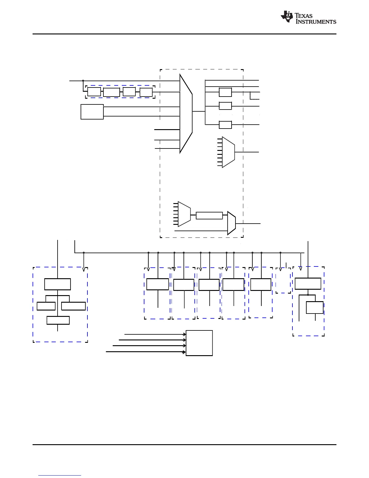
6.6.2.2 Mapping of Clock Domains to Device Modules
Each clock domain has a dedicated functionality as shown in Figure 6-7 .
Figure 6-7. Device Clock Domains