1
1
2
2
3
3
4
4
5
5
6
6
7
7
8
8
9
9
10
10
A
A
B B
C C
D D
E E
F F
/ 400
COMMON
Isense_W
/ 400
Iref_G
P1
P_ref
400
P_ref
P_ena
200
GNDW
COM
GND_C
Isense_W
PGND2
/ 200
-15Vw
TEMP_C
-15V
INPUT_NG
I_senseP
+5V
GND
+15V
+15V
Iref_G
GNDW
+15Vw
P_ena
GND_C
TEMP_C
PGND1
+15V
MISSING_PHASE
COM_A
GNDP
200_A
N2
+15Vw
GNDP
400_A
+12V
-15Vw
-12V
I_senseP
SIGNAL
TORCH (-)
PILOT
WORK (+)
E
L1
L2
L3
+12VDC+12VDC
+15V
+12VDC
To PCB7 TB3
To T1 PRI - 0
FAN + (24 VDC)
NEG ARC VOLTS
To PCB7 CN2-5
FAN - (24 VDC)
WORK
From CN9 on PCB7
To PCB7 CN2-4
To PCB7 CN2-2
To PCB7 CN2-1
PILOT (TIP) VOLTS
DWG No:
Sheet
of
SupersedesScale
Date:
Drawn: References
Date
By
Revisions
Rev
PCB No:
Assy No:
Information Proprietary to THERMAL DYNAMICS CORPORATION.
Not For Release, Reproduction, or Distribution without Written Consent.
NOTE: UNLESS OTHERWISE SPECIFIED -
1. RESISTOR VALUES ARE EXPRESSED IN OHMS, 1/4W 5%.
2. CAPACITOR VALUES ARE EXPRESSED IN MICROFARADS (uF). Chk: App:
TITLE:
Last Modified:
Size
SCHEMATIC,
Thermal
Dynamics
AA
42X1312
Friday, January 18, 2008
1 2
Industrial Park #2
West Lebanon NH 03784
603-298-5711
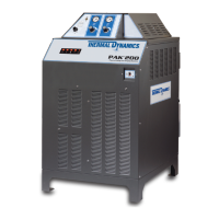
PAK 200 Power Supply 400V non-CE
Thursday, January 10, 2008
12:56:07
Thermal Dynamics
D
DWG No:
Sheet
of
SupersedesScale
Date:
Drawn: References
Date
By
Revisions
Rev
PCB No:
Assy No:
Information Proprietary to THERMAL DYNAMICS CORPORATION.
Not For Release, Reproduction, or Distribution without Written Consent.
NOTE: UNLESS OTHERWISE SPECIFIED -
1. RESISTOR VALUES ARE EXPRESSED IN OHMS, 1/4W 5%.
2. CAPACITOR VALUES ARE EXPRESSED IN MICROFARADS (uF). Chk: App:
TITLE:
Last Modified:
Size
SCHEMATIC,
Thermal
Dynamics
AA
42X1312
Friday, January 18, 2008
1 2
Industrial Park #2
West Lebanon NH 03784
603-298-5711
PAK 200 Power Supply 400V non-CE
Thursday, January 10, 2008
12:56:07
Thermal Dynamics
D
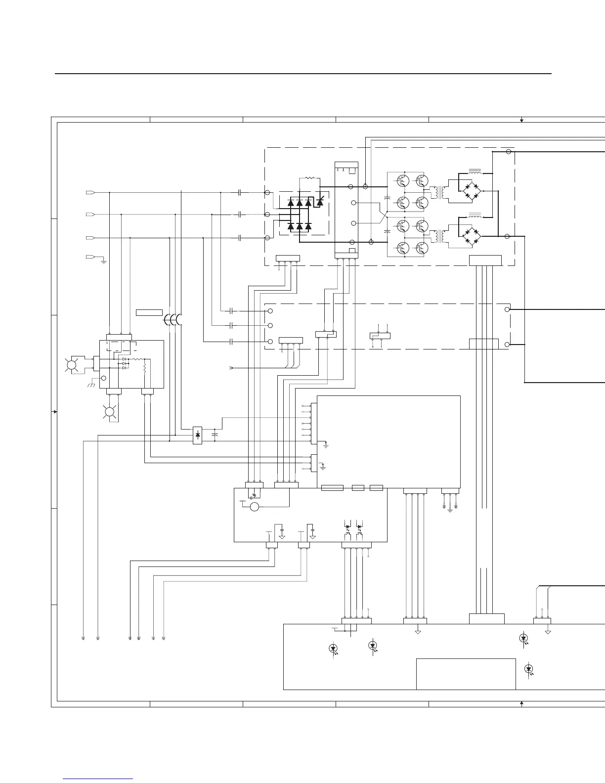
RAS
< /OVER_TEMP
(C7, Sht 2)
400 VAC 3 Phase
CN1
CN5 CN6
CN4
BIAS SUPPLY PCB
DETECTOR PCB
INPUT POWER
INDICATOR
REAR PANEL
CN5
> P_DEM (P_Iref)
INPUT POWER
INDICATOR
INTERNAL
VAC_IN
(A1 Sht2)
(A1 Sht2)
> P_Enable (P_ena)
CN6
RIBBON CABLE SIGNALS
CN6 - 16 Ckt Ribbon Cable
2,4- I_REF (Scaled Cut Demand)
5- PS_START (Start)
6- REDUNDANT_START (Start2)
8- INV_READY
9- / PS_START disabled by Input_NG
12- / OCR
13- / PS_START disabled by OCR
14- /TEMP_ERR
15- / PS_START disabled by Temp _Err
DAT
INTERFACE PCB
FILTER PCB
P_GND
PILOT REG.
(CHOPPER )
PCB2
WK-5754
(A1 Sht 2)
(A1 Sht 2)
HALL SENSOR
BIAS
POWER
C1 Capacitor, 0.1 uf, 1250 VDC (D2, Sht 2)
C2 Capacitor, 2 uf, 430VAC (A9, Sht 1)
C.P1 Circuit protector/ON-OFF SW (B2, Sht 1)
15A, 460V, 3P
C.P2 Circuit protector 2.5A 125V (D2, Sht 1)
C.P3 Circuit protector 3.15A 125V (D2, Sht 1)
C.P4 Circuit protector 10A 125V (E2, Sht 1)
C.P5 Circuit protector 2.5A 125V (E2, Sht 1)
C.P6 Circuit protector 2.5A 125V (F2, Sht 1)
C.P7 Circuit protector 5A 125V (E2, Sht 1)
C.P8 Circuit protector 3.15A 125V (F3, Sht 1)
D1 Diode Bridge 20A, 1600V, 3P (D2, Sht 1)
D2 Diode, Dual, 2x100A, 600V (B8, Sht 1)
FAN1 Fan, Coolant, 24 VDC (F4, Sht 2)
FAN3 Fan, Chopper, 24 VDC (A8, Sht 1)
FL1 Flow sensor (B5, Sht 2)
(D2, Sht 2)
V_CHANGE PCB
400V only
I_DET
HCT1 Hall Current Sensor, Pilot (B8, Sht 1)
HCT2 Hall Current Sensor, Work (C9, Sht 1)
LSW1 Level SW, coolant, NC (B5, Sht 2)
MC1 Contactor, 3P ,Inv 1 input, Coil (B3, Sht 2)
" Contacts (A2, B2, Sht 1)
" Aux Contact (B3, Sht 2)
MC2 Contactor, pilot, Coil (B3, Sht 2)
" Contacts (C8, Sht 1)
MC3 Contactor, 3P ,Inv 2 input, Coil (B3, Sht 2)
" Contacts (B2,C2, Sht 1)
" Aux Contact (B3, Sht 2)
MOT1 Motor, Pump 200VAC, 1P (E4, Sht 2)
NE1 Neon indicator, rear panel, 220VAC (C1, Sht 1)
NE2 Neon indicator, internal, 220VAC (C1, Sht 1)
R1a-f Resistor Pilot 0.6, 300W , (B8, sht 1)
(6 in series)
R6 Resistor, 20K ,30W (A8, Sht 1)
R7 Resistor, 1K ,30W (E2, Sht 2)
R9 Resistor, 50 ,40W (A9, Sht 1)
T1 Aux Transformer (D-F1, Sht 2)
TH1 Thermal Sensor, coolant return (B5, Sht 2)
ON / OFF
<
LINE to LINE,
LINE TO GND
CAPS & VARISTORS
I_SE
PILOT REG.
(CHOPPER )
PCB1
WK-5750
<
PCB 1
WK-5630
(C7 & A9,Sht 2)
HALL SENSOR
COMPONENT LOCATOR
16 CKT RIBBON CABLE
100A INVERTER MODULE # 1 (top)
PILOT CURRENT SIGNAL <
WORK CURRENT SIGNAL <
/ OVERTEMP <
CN6
PCB 5 WK-5602 (partial)
MISSING PHASE
(pulses)<
(C7 & A9,Sht 2)
LED1 DIM = LOW, BRIGHT = OK
LED2 DIM = OK, BRIGHT = FAULT
LED3 DIM = OK, BRIGHT = FAULT
LED4 OFF = OK, ON = FAULT
LED5 OFF = OK, ON + FAULT
/PILOT ENABLE >
PILOT DEMAND >
CN6 16 CKT
CN6
PILOT REGULATOR
(CHOPPER)
P_GND
VAC_IN
Power Supply
Rear Panel
PCB3 WK-5694
PCB4 WK-5604
BIAS SUPPLY
FOR PCB5
(F2 -Sht2)
100A INVERTER MODULE # 2 (bottom)
(same as #1)
--400--
DC FAN
POWER
(A2 Sht 2)
(A2 Sht 2)
PCB 8
WK-5687
RC &
RF CAPS
For this
version
of the
power supply
Pilot
Regulator
is not used
except to
provide power
and pass
signals from
HCT1, the
pilot current
sensor.
Pilot
Resistors,
R1a-f, are
used instead.
ECO-B731 (REL) DAT
1-18-08
THS1
SW_TEMP_NC
THS1
SW_TEMP_NC
++
- +- +
3
1
2
4
MC3-BMC3-B
TB4TB4
R6
20K
30W
R6
20K
30W
CN1CN1
1
2
3
4
TB2TB2
CN7CN7
1
2
3
4
5
CN10CN10
1
2
CN1CN1
1
2
3
4
CN32CN32
1
2
3
4
1
2
3
4
CN4CN4
1
4
LED2
MISSING PHASE
LED2
MISSING PHASE
C4C4
MC1-AMC1-A
CN9CN9
1
2
TB1TB1
CN4CN4
1
2
3
4
5
LED3
INPUT NG
LED3
INPUT NG
CN32CN32
1
2
3
4
C2
2 UF
C2
2 UF
CN1CN1
1
5
8
NE1NE1
CN33CN33
1
2
3
4
CN17CN17
1
2
3
CN2CN2
1
2
3
CN1- not used
6
CN1- not used
6
1
2
3
4
CN2CN2
1
2
SS
SS
CN2CN2
1
2
3
4
RR
C2C2
1
2
3
CN18CN18
1
2
3
MC2-CMC2-C
R1R1
INRUSHINRUSH
NE2NE2
CN2 400VCN2 400V
1
2
3
4
+
RY2
RY2
+
RY2
RY2
RY2RY2
+
-
+
-
1
2
3
45
6
TB2TB2
HCT2HCT2
1
2
3
4
CN1- not usedCN1- not used
1
2
3
4
N2N2
CN7CN7
1
2
3
4
5
MC1-BMC1-B
CN3CN3
1
2
3
4
R9
50
R9
50
TB1TB1
T1T1
TB4TB4
- +- +
3
1
2
4
C.P1C.P1
CN4 - PCB12CN4 - PCB12
1
2
3
4
P1P1
R1 a-f 3.6
(6 x 0.6, 300W in series)
R1 a-f 3.6
(6 x 0.6, 300W in series)
P (+)P (+)
N (-)N (-)
CN5CN5
1
2
3
4
TT
P (+)1P (+)1
MC2-BMC2-B
200V200V
++
TB3TB3
CN6CN6
1
2
3
TB1TB1
MC2-AMC2-A
1 2
34
CN1CN1
1
2
3
4
5
6
7
CN5CN5
1
2
3
4
TB5TB5
MC3-AMC3-A
LED4
CHOPPER TEMP
LED4
CHOPPER TEMP
MC3-CMC3-C
CN1CN1
1
2
CN7CN7
1
2
3
4
5
CN8CN8
1
2
CN3CN3
1
CN4CN4
1
2
3
CN3CN3
1
2
CN4CN4
1
2
3
4
N (-)1N (-)1
HCT1HCT1
1
2
3
4
LED5
ERROR
LED5
ERROR
TB1TB1
FAN3FAN3
+ -
CN2-400VCN2-400V
1
2
3
4
TB2TB2
D2D2
1
A1
2
K1
3
A2
4
K2
CN4 - PCB12CN4 - PCB12
1
2
3
4
CN3CN3
1
2
CN2CN2
1
2
3
TB3TB3
AC
AC
AC
+-
D1
AC
AC
AC
+-
D1
WORKWORK
CN4CN4
1
2
3
4
5
MC1-CMC1-C
CN3CN3
1
4
CN2CN2
1
2
3
Art # A-08488
Art # A-08488