Manual 0-5057 2-1 SPECIFICATIONS
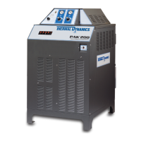
PAK 200
2.01 General Description Of The System
A typical PAK200
®
plasma cutting system includes:
• One Power Supply
• Arc Starter / Gas Control Module (Mounted on Power Supply)
• General Purpose Plasma Cutting Torch with Connecting Leads
• Torch Spare Parts Kit
• Work Cable with Clamp Air Hose (see assembly)
The components are connected at installation.
2.02 Plasma Power Supply
The power supply provides the necessary current for cutting operations, and monitors system performance. The
power supply also cools and circulates the liquid coolant for the torch and leads.
2.03 Gas Control Module / Arc Starter
This module mounts to the top of the power supply. This module enables the operator to select gas, set pressures
and flows and set cutting current.
2.04 Plasma Cutting Torch
The torch delivers the controlled current to the work through the main arc, causing the metal to be cut.
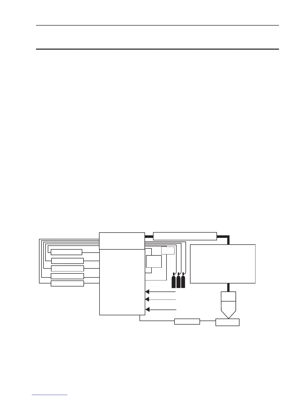
2.05 System Component Layout
Primary power
Control
Cable
Ground
Cable
Work
Art # A-08376_AB
Torch
Work Cable
PAK 200
Power Supply
Arc Starter /
Gas Control Module
(GCM-200)
Pilot Return
Negative
Coolant Supply
Coolant Return
Control Cable
Torch Lead Set
- Coolant Supply w/ Negative
- Coolant Return
- Pilot Return
- Plasma Gas
- Shield Gas
- Control Cable
Maximum Length 100’ / 30.5 m
Primary Ground
SECTION 2:
SPECIFICATIONS