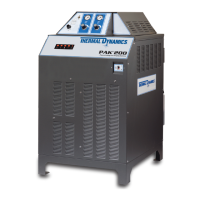
PAK 200
Manual 0-5057 4-1 OP-
SECTION 4:
OPERATION
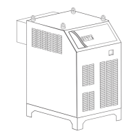
4.01 Power Supply Indicators
Art # A-04813
AC Indicator
Temp Indicator
Gas Indicator
DC Indicator
Status Indicator
AC Power Indicator
Indicates AC power is being supplied to the inverters when the ON/OFF switch is in ON position. When switch is
first set to ON, the indicator stays off until the inrush cycle is complete and the correct voltage is confirmed.
TEMP Indicator: Normally OFF. Indicator turns ON when the internal temperature sensors detect tempera-
tures above normal limits. Let the unit cool before continuing operation.
GAS Indicator: The indicator blinks when the gas control is not ready. Causes for not being ready are when
purging, Run/Set switch is not set to Run, gas pressure is not correct. When gas flow is called for (preflow,
cutting, postflow ) the indicator is on steady. It is off at all other times.
DC Indicator: Indicates the power supply is generating output DC voltage.
Status Indicator: Shows system status. The number of flashes indicates the status. Refer to the
Status Code Section for details. On power supply start-up, the indicator flashes to show the revision level of
the operating software installed in the system.