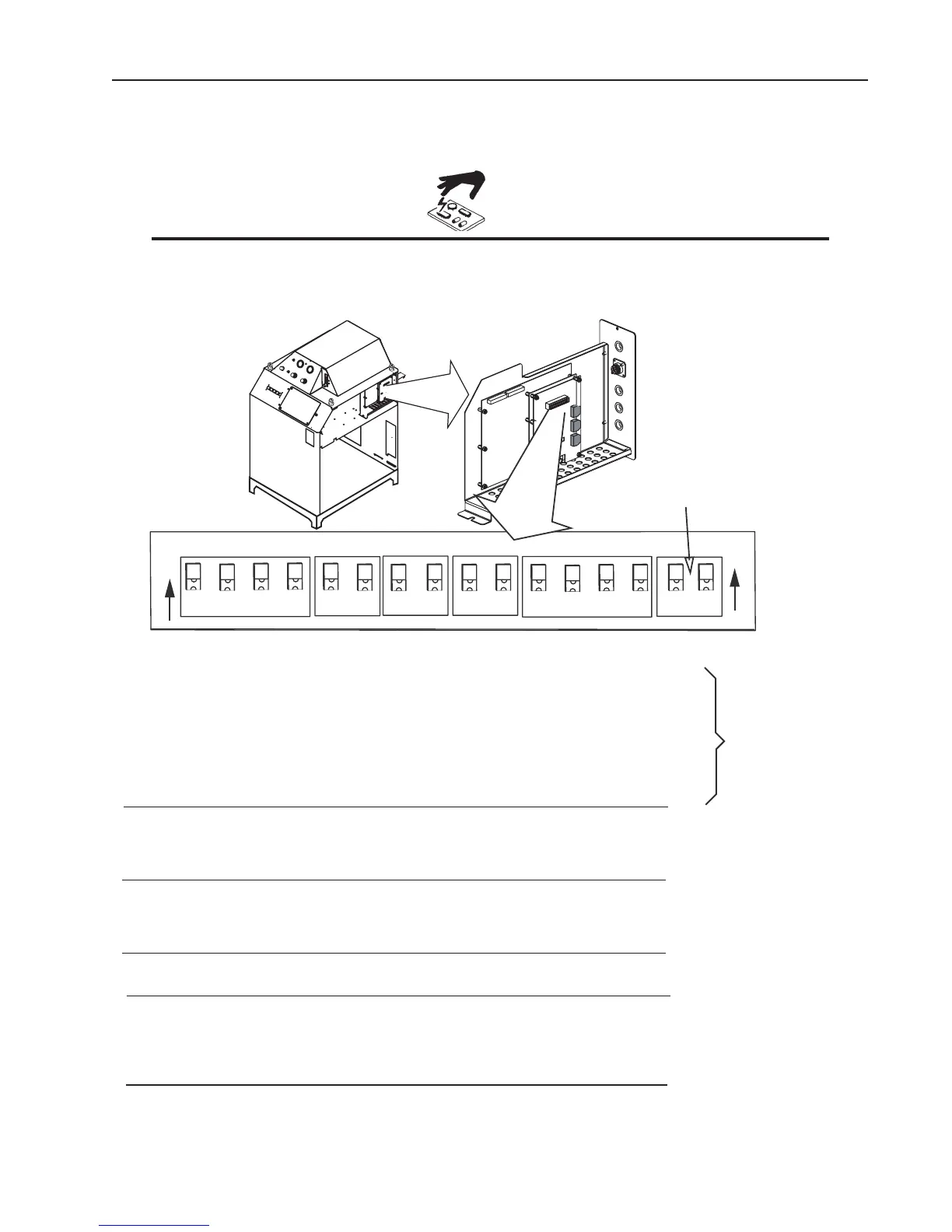
Remove the power supply right side. Set switches on the CCM (Command-Control Module) per the illustrations.
Switch settings and connection details are provided in the Appendix.
static charges in you body or surroundings before touching the printed circuit boards.
SW1
SW3
SW4
SW5
SW8
3
4
1
2
3
4
1
2
1
2
1
2
1
2
1
2
S
W-1-1: Auto Pilot Restart. 1 = ON = Auto Pilot Function enabled. (Factory default setting).
1 = OFF = Auto Pilot Function disabled
SW-1-2: Pilot Delay 2 = OFF, 3 = OFF, 4 = OFF: 0 Seconds (Factory default setting).
SW-1-3: Pilot Delay 2 = ON,
3 = OFF, 4 = OFF: 0.1 Seconds
SW-1-4: Pilot Delay 2 = OFF, 3 = ON, 4 = OFF: 0.2 Seconds
2 = ON,
3 = ON, 4 = OFF: 0.4 Seconds
2 = OFF, 3 = OFF, 4 = ON: 0.8 Seconds
2 = ON,
3 = OFF, 4 = ON: 1.0 Seconds
2 = OFF, 3 = ON, 4 = ON: 1.5 Seconds
2 = ON, 3 = ON, 4 = ON: 2.0 Seconds
SW-4: Postflow Time 1 = OFF, 2 = OFF: 10 Seconds (Factory default setting).
1 = ON,
2 = OFF: 20 Seconds
1 = OFF, 2 = ON: 5 Seconds
1 = ON, 2 = ON: 0 Seconds
SW-5-1: Tip Saver SW5-1 not used, Tip Saver always on.
SW-5-2: Off Plate Reserved for Factory use.
SW 8-1: Pilot Time 1 = ON = Short (85 ms.)
1 = ON = Long (3 s.)
O
N
O
N
Active only when
SW-1-1 is set to O N.
Art # A-08379_AB
Future Use
SW-3: Gas Preflow Time 1 = OFF, 2 = OFF: 2 seconds
(Factory default setting).
1 = ON, 2 = OFF: 4 seconds
1 = OFF, 2 = ON: 6 seconds
1 = ON, 2 = ON: 8 seconds
SW 8-2: Remote Current 2 = OFF = Front panel current control (Factory default setting).
2 = ON = (Remote Analog Current Control) See also SW11
SW 8-3, SW8-4: Reserved for Factory use.