Art # A-04900
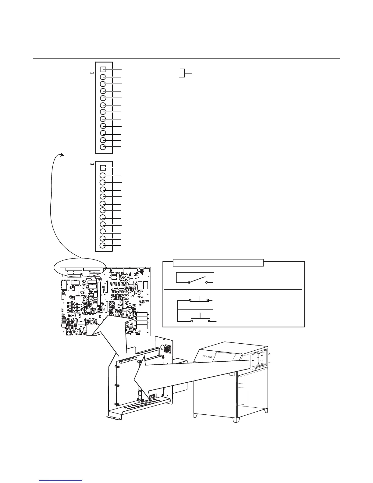
TB1-1 E-Stop (Com)
TB1-2 E-Stop
TB1-3
TB1-4 Stop Latched
TB1-5 Start / Stop Ret
TB1-6 Start / Stop or Start Latched (NO)
TB1-7 Divided Arc Voltage (-)
TB1-8 Divided Arc Voltage (+)
TB1-9 Remote Analog Current Control (0-10V) (-)
TB1-10 Remote Analog Current Control (0-10V) (+)
TB1-11
TB1-12
TB2-1 Hold Start (-)
TB2-2 Hold Start (+)
TB2-3 Preflow On (-)
TB2-4 Preflow On (+)
TB2-5
TB2-6 Pilot On (Relay Contacts NO)
TB2-7
TB2-8 Pilot On (Relay Contacts NO)
TB2-9
TB2-10 OK to Move (Contacts or DC Volts) (-)
TB2-11
TB2-12 OK to Move (Contacts or DC Volts) (+)
TB2
TB1
Sustained Start / Stop
TB1-5
TB1-6
Momentary Start / Stop
TB1-4
TB1-5
TB1-6
Stop
Start
Start / Stop Circuit Configurations
These points are jumpered together at the factory.
Remove the jumper to use existing E-Stop circuits.