Refrigeration Maintenance
128
Set Up and Test of Evacuation
Equipment
NOTE: See the previous two pages for the
following discussion.
1. Connect the evacuation system to a 110 Vac
power supply. Connect a gauge manifold and
refrigerant supply to the charging port above
valve V-4. Turn the micron gauge On.
2. Close valves V-1, V-3 and V-4. Valve V-2 is
open.
3. Turn the vacuum pump On.
4. Open valve V-1 at the pump. The micron
gauge needle will move to the left. (See
micron gauge scale diagram—previous page).
NOTE: If the vacuum pump is okay, and
there are no leaks between V-1 and V-3, the
micron gauge should show less than 500
microns. If not, locate and correct the
problem.
5. With the pump still operating, open valve V-3.
If the micron reading does not return to a level
of less than 500 microns, locate and correct
the problem before continuing.
6. With the vacuum pump still operating, open
valve V-4. The micron level will rise
momentarily. If the micron reading does not
return to a level of less than 500 microns,
locate and correct the problem before
continuing.
7. Evacuate hoses to 100 microns or lowest
achievable level below 500 microns.
8. Once 100 microns is reached, close valve V-1
at the pump. Turn the vacuum pump Off.
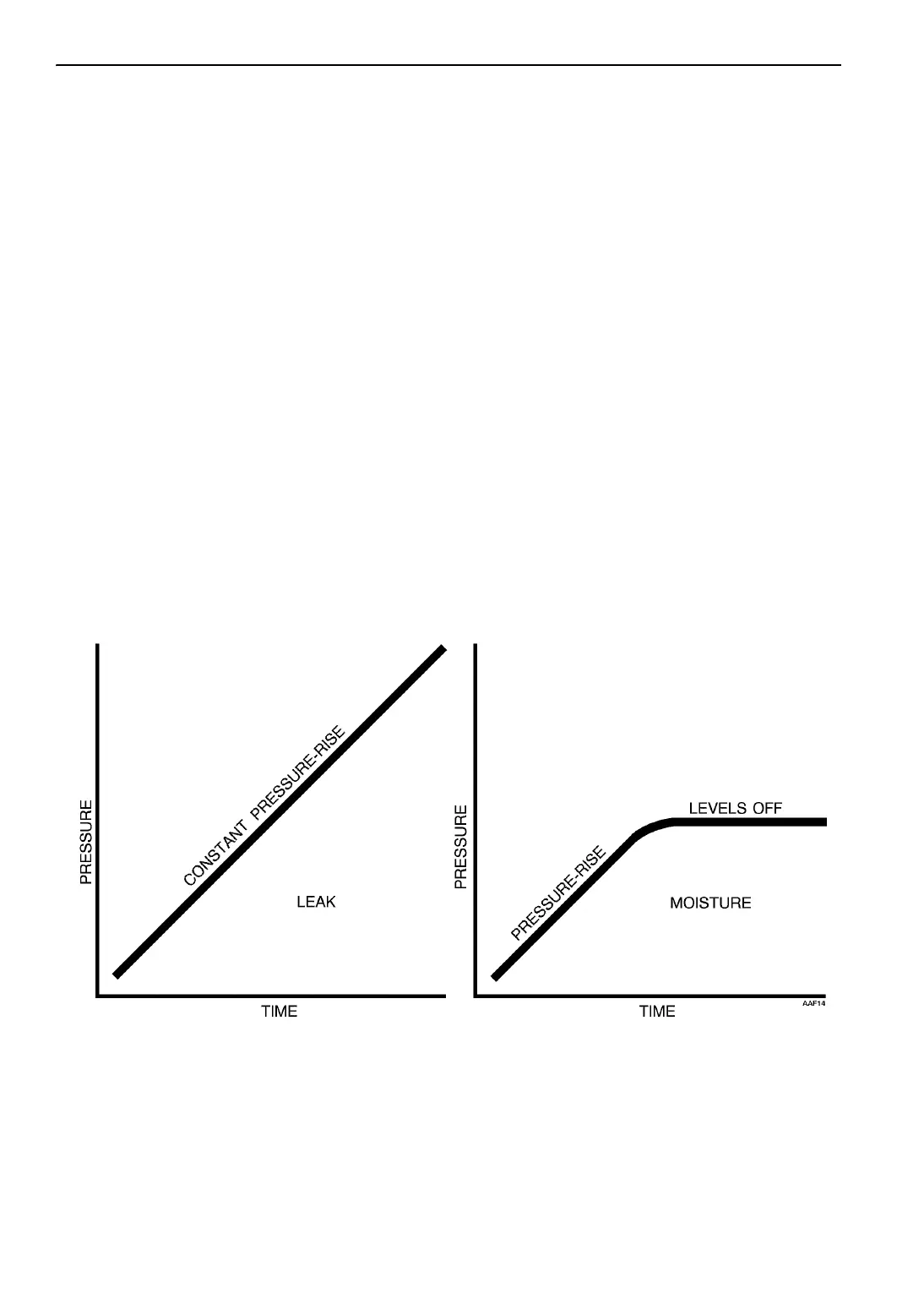
Figure 152: Pressure Rise Graphs
Leak
Isolate the pump from the system by closing the
proper valve. Watch the movement of the vacuum
gauge needle. If the needle continues to rise,
this is an indication that a leak exists in the unit
or the connecting line. The leak must then be
located and eliminated.
Moisture
Should the needle show a pressure rise but
finally level off to practically a constant mark,
this is an indication that the system is vacuum
tight but is still too wet, requiring additional
dehydration and pumping time.
 Loading...