Electrical Maintenance
85
NOTE: On installations where the unit is
connected to the truck battery and both units are
running—it is normal for the unit to indicate a
discharge condition while the truck engine is
running because of the truck’s higher voltage
charge rate.
Preheat Buzzer
The preheat buzzer module on the circuit board is
designed to indicate preheat is in operation.
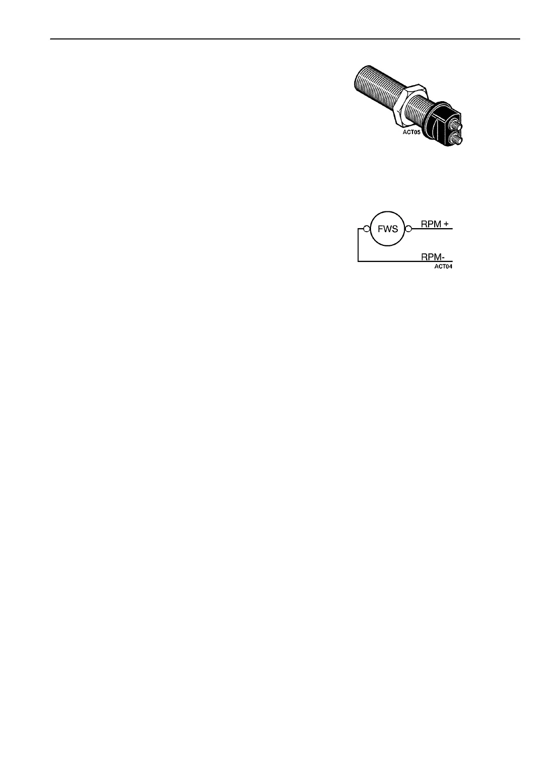
RPM Sensor
The RPM sensor is in the engine bell housing
adjacent to, but not touching, the flywheel
(backed off 1/4 turn).
The RPM sensor is a device containing an
inductance coil and magnet. When the magnetic
field is distorted by the passing ring gear teeth, the
inductance coil generates an ac electrical signal
that has a voltage and frequency variation
proportional to the engine RPM.
By monitoring the frequency of this signal with
the microprocessor, the timing of the starter
disengagement can be precisely controlled.
If the RPM sensor fails, the starter may not
disengage or engage properly and a fault code will
be generated to the microprocessor.
Testing the RPM Sensor:
The following equipment is required:
• AC voltmeter capable of reading up to 10
volts
• Ohmmeter
The flywheel (RPM) sensor may be checked as
follows:
1. Install the flywheel (RPM) sensor into the
flywheel; bracket of the start-stop unit until it
contacts the ring gear. Back out the sensor 1/4
turn and tighten the locknut.
Figure 114: Flywheel (RPM) Sensor
2. Disconnect wires RPM+ and RPM- from the
sensor.
Figure 115: RPM+ and RPM- Wires
3. Place the unit in Continuous Run. Run the unit
on low speed and high speed. Check the AC
voltage output across the sensor terminals.
Use a meter with a high ohms per volt internal
resistance. A Simpson 260, Fluke digital or
any good VOM will work. However, an
automotive type meter may not give an
accurate reading because the meter may load
the circuit heavily and cause the voltage level
to appear lower than it actually is.
a. The output voltage should be 1.0 to
2.0 Vac on low speed.
b. The output voltage should be 2.0 to
2.5 Vac on high speed.
NOTE: If the voltage is slightly off, the
voltage may be increased by turning the
sensor in more, and the voltage may be
lowered by turning the sensor out more.
4. Reconnect RPM+ and RPM- wires on RPM
sensor.
If the RPM sensor passes the above test, the
sensor may be considered good.
If the unit is not available, an alternate less
reliable test may be performed as follows:
Disconnect the sensor from all wires, and measure
the resistance across the terminals and from each
terminal to the aluminum case. The resistance
 Loading...