Engine Maintenance
108
1. Rotate the engine in the direction of rotation
(clockwise as viewed from the water pump
end) until the number 1 cylinder (closest to
flywheel) is at approximately top dead center
of the compression stroke. The valve cover
should be removed to identify the
compression stroke. Both rocker arms of the
number 1 cylinder will be loose. Check to see
that the number 1 cylinder top dead center
mark on the flywheel is aligned with the
timing mark on the starter mounting plate.
NOTE: The timing marks for each of the
three cylinders are stamped 120 degrees
apart. Top dead center marks are identified
by the number of the cylinder stamped next
to them. Injection timing marks are
unmarked. The timing marks on the engine
can be difficult to align. This is because the
timing mark on the starter mounting plate is
near the air cleaner, on the side of the plates
that faces the flywheel. It cannot be seen
when looking through the engine side door
opening unless you use a mirror.
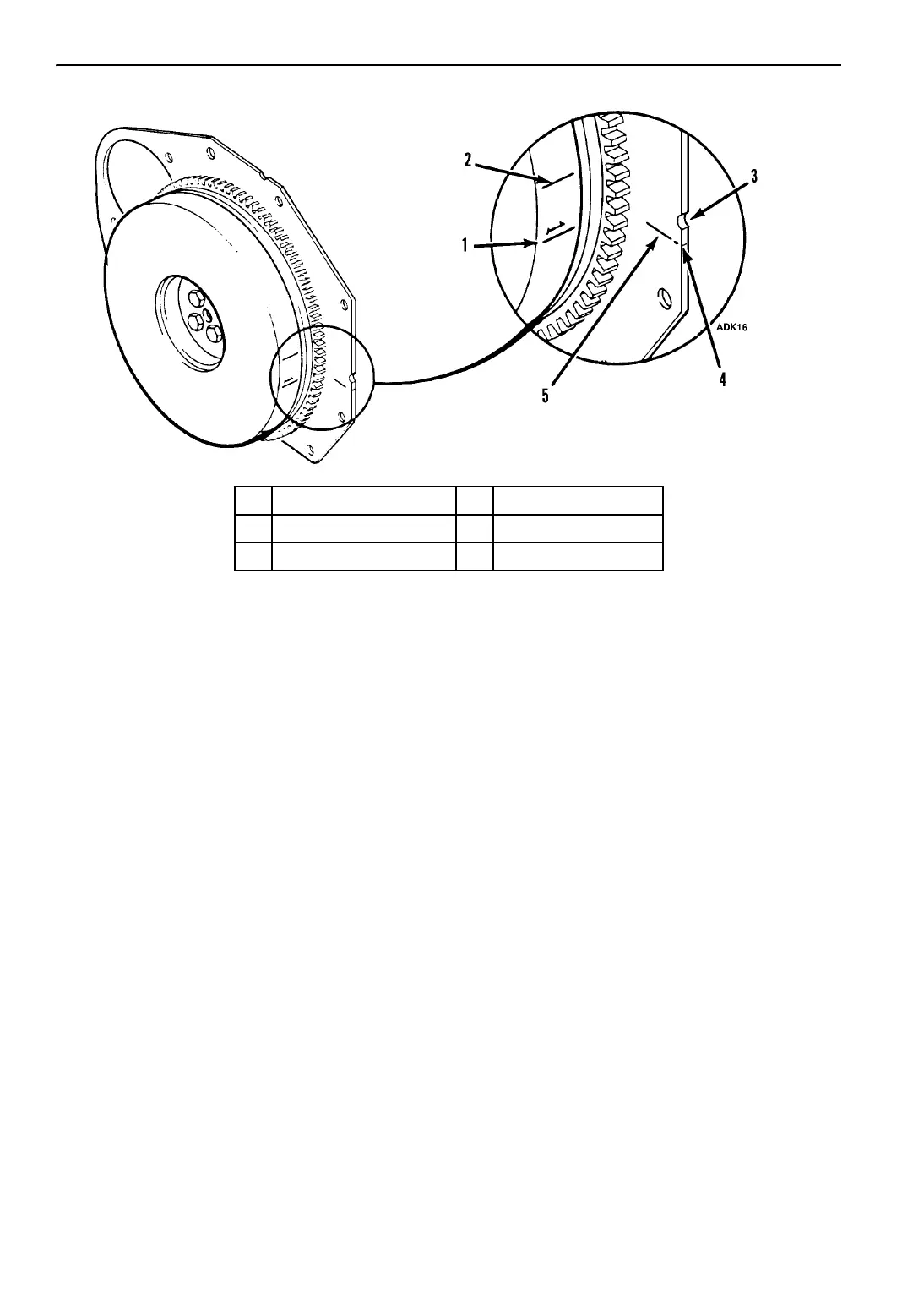
The timing mark on the starter mounting
plate is a line stamped on the side of the plate
facing the flywheel. To locate the timing
mark, feel the back side of the plate 0.4 in.
(10 mm) below the center of round notch in
the edge of the plate. To make it easier to
align the timing marks, file a V-notch in the
edge of the plate in line with the timing mark
on the plate.
2. Remove the injection line from the number 1
injector and the injection pump. Remove the
delivery valve holder, delivery valve and
spring. Care must be taken to prevent dirt
from entering the fuel injection system.
Replace the delivery valve holder and delivery
valve.
3. Install a drip valve on the nozzle holder.
4. Activate the fuel solenoid and the fuel pump
by energizing the run relay using the Interface
Board Test mode. Make sure the
Diesel/Electric switch is in the Diesel
position. See the SPECTRUM TS
Microprocessor Diagnostic Manual, for
information about the Interface Board Test
mode.
1. TDC Mark 4. File V-Notch Here
2. Injection Timing Mark 5. Timing Mark
3. Round Notch
Figure 134: Timing Marks
 Loading...