Unit Description
41
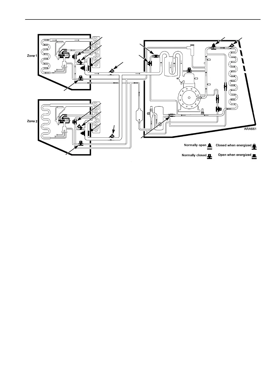
Figure 12: Zone 1 Cool and Zone 2 Null
Zone 1 Cool and Zone 2 Null
High pressure refrigerant vapor leaves the
compressor and flows through the open CIS to the
condenser, where refrigerant condenses into high
pressure liquid. The liquid refrigerant flows
through the receiver tank into the Zone 1 liquid
line.
The LLS1 is open so the refrigerant flows through
the Zone 1 expansion valve into the Zone 1
evaporator. There, the liquid refrigerant cools the
Zone 1 evaporator as it evaporates into low
pressure vapor. The refrigerant returns to the
compressor through the SLS1, suction line,
SLCV1 and the accumulator.
The LLS2 is closed, which prevents refrigerant
from reaching the Zone 2 evaporator.
Zone 1 Evaporator
1F. Zone 1 Liquid Line Solenoid (LLS1)-Open
2F. Zone 1 Liquid Return Check Valve
(LRCV1)-Closed
3F. Zone 1 Suction Line Check Valve
(SLCV1)-Open
4F. Zone 1 Suction Line Solenoid (SLS1)-Open
5F. Zone 1 Hot Gas Solenoid (HGS1)-Closed
Zone 2 Evaporator
1R. Zone 2 Liquid Line Solenoid (LLS2)-Closed
2R. Zone 2 Liquid Return Check Valve
(LRCV2)-Closed
3R. Zone 2 Suction Line Check Valve
(SLCV2)-Open
4R. Zone 2 Suction Line Solenoid (SLS2)-Open
5R. Zone 2 Hot Gas Solenoid (HGS2)-Closed
Condensing Unit
6. Condenser Inlet Solenoid (CIS)-Open
7. Condenser Inlet Check Valve (CICV)-Open
8. Condenser Check Valve (CCV)-Open
9. Purge Valve (PV)-Closed
10. Purge Check Valve (PCV)-Closed
1F
2F
4F
3F
9
6
7
8
3R
5R
4R
2R
1R
5F
10
 Loading...