Unit Description
57
Power Supply Board
The power supply board provides regulated DC
power to the microprocessor and interface board.
It is separate from the other boards due to
manufacturing considerations and to allow the
capability to be increased as required for future
applications.
If the LED on the power supply board is
illuminated the power supply board is functioning
normally.
Figure 28: Power Supply Board
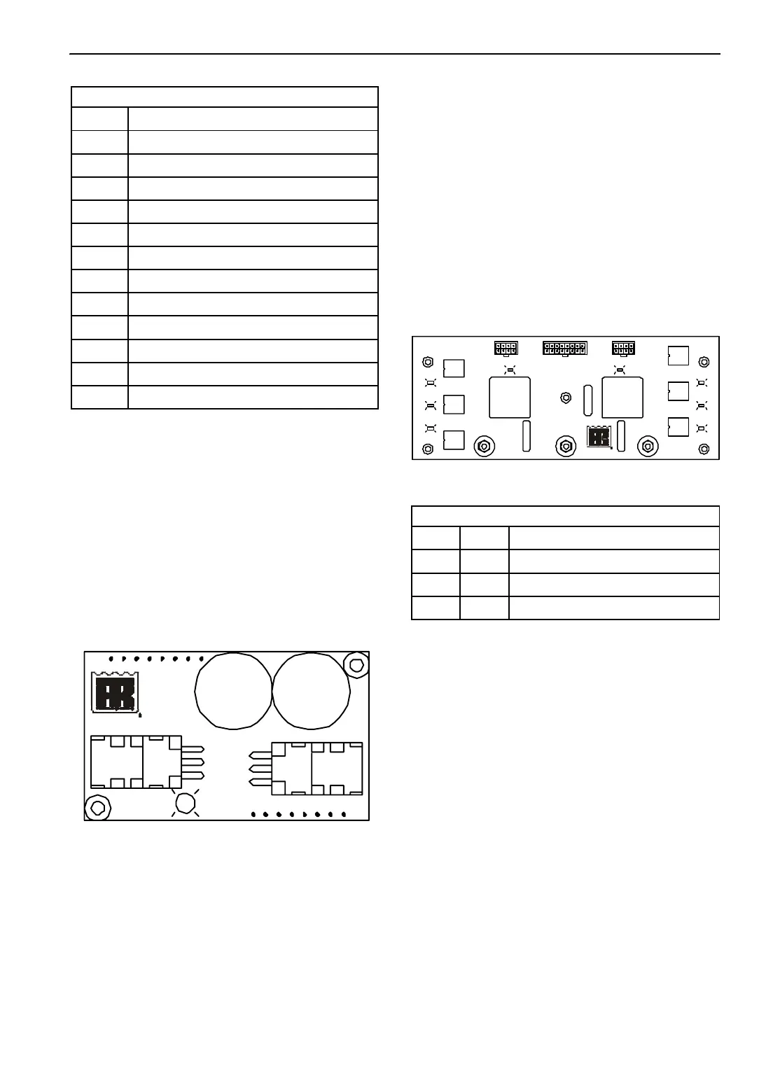
Multi-Temp Option Board
The Multi-temp Option Board adds the control
functions for Zone 2 and Zone 3. The
microprocessor controls the operation of the
additional zones through the control relays on the
multi-temp option board. An LED is illuminated
when a relay is energized by the microprocessor
and has transferred its contacts to the energized
state.
The only user serviceable components on the
“multi-temp option board” are the fuses and
jumpers.
Figure 29: Multi-Temp Option Board
Interface Board Relay Functions
Relay Function
K1 Alternator Excitation Relay
K2 Zone 1 Fan Relay
K3 Starter Relay
K4 Fuel Solenoid Pull In Relay
K5 Throttle Solenoid Relay
K6 On/Off Relay
K7 Run Relay
K8 Zone 1 Hot Gas Solenoid Relay
K9 Preheat Relay
K10 Diesel/Electric Relay
K13 Zone 1 Liquid Line Solenoid Relay
K14 Zone 1 Suction Line Solenoid Relay
P1
P2
LED1
Multi-Temp Option Board Fuse Size and Function
Fuse Size Function
F200 15A 2A Power Zone 2
F201 1A Zone 2, 3 Door Switch 2A Power
F202 15A 2A Power Zone 3
FM32AFM2
K205
K206
K207
K202
K203
K204
K200 K201
15
15
1
P202P201 J1
F202
F201
F200
SLS3
LLS3
HGS3
SLS2
LLS2
HGS2
FAN 2 FAN 3
 Loading...