Engine Maintenance
114
Engine Mounts
TK 3.95 Engine
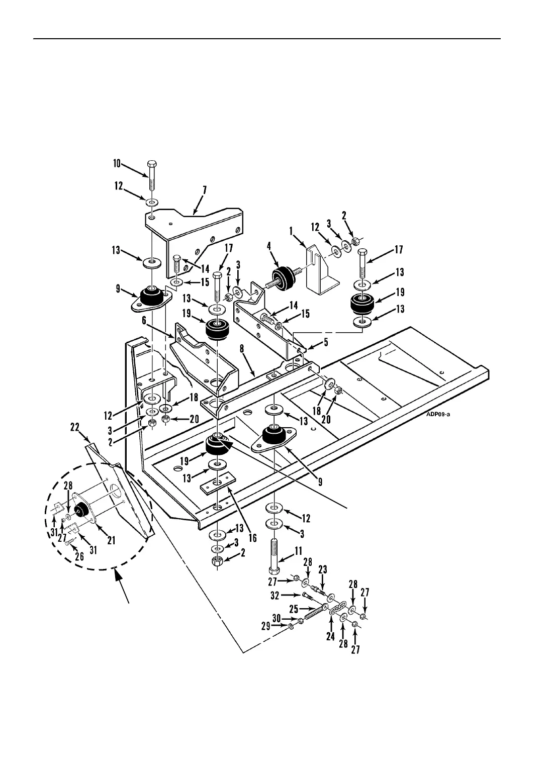
The engine mounting system for the TK 3.95
engine contains three vibration mounts, two
snubber mounts, and a chain restraining mount.
Figure 142: TK 3.95 Engine Mounting Components
NOTE: For details see
“Chain/Restraining Mount”
on page 118.
0.20 Air Gap Between Lower
Snubber and Engine Bracket
When Assembled
(Snubbers Only)
 Loading...