Refrigeration Maintenance
130
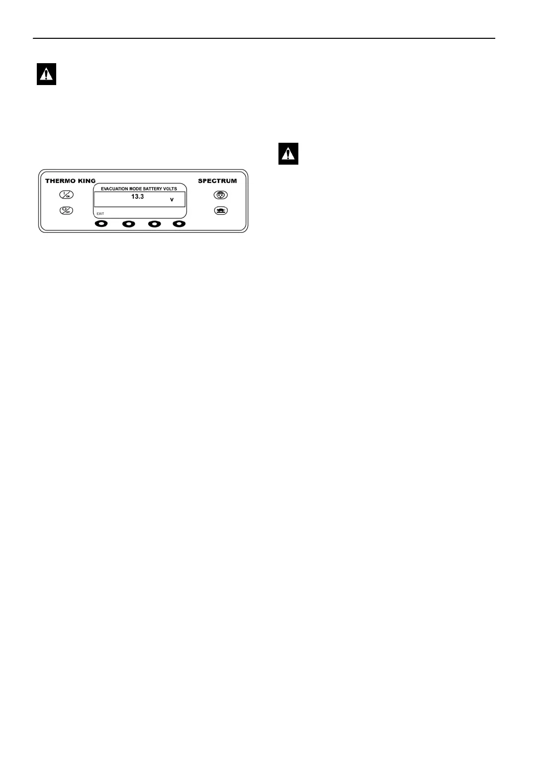
The battery voltage is shown and all normally
closed refrigeration valves are opened. They will
remain open until the EXIT key is pressed or the
battery voltage falls below a minimum voltage.
Figure 158: Battery voltage
Proceed with system leak check or evacuation.
Leak Check System
NOTE: Refer to Diagnosing Thermo King
Refrigeration Systems (TK-5984-10) for leak
detection procedures.
1. Put the unit into Evacuation Mode (see “Using
The Evacuation Mode Menu” on page 129).
2. Connect leak test gas (R-404a) supply to
center hose of gauge manifold.
3. Attach gauge manifold hoses to the suction
service valve and the discharge service port. A
low loss fitting must be used on the hose
connected to the discharge service port.
4. Pressurize the system with leak test gas. If
desired, system pressure may be boosted using
nitrogen gas.
5. Check connections made during installation
for leaks using electronic leak detector and/or
soap bubbles.
6. Recover test gas to repair leaks. System must
be vented while repairing solder joint leaks.
Pressurize system and check again after a leak
has been repaired.
7. If no leaks are found recover test gas to 0 psi.
Unit Evacuation
NOTE: Do not attempt to evacuate the unit until
the evacuation equipment has been tested and its
performance has been verified.
1. Prepare the unit for evacuation. Recover
refrigerant to 0 psig (0 kPa).
NOTE: New Federal Regulations may
require your recovery machine to pull the
system’s pressures lower than 0 psig [0 kPa].
2. Put the unit into Evacuation Mode (see “Using
The Evacuation Mode Menu” on page 129).
3. Install the evacuation station hoses on the
receiver tank outlet valve, suction service
valve, and discharge service port. A low loss
fitting must be used on the hose connected to
the discharge service port.
4. Mid-seat the receiver tank outlet valve and
suction service valve, and install the valve
stem caps.
5. Connect a gauge manifold and refrigerant
supply to the charging port above valve V-4.
Bottle valve closed.
6. Start the vacuum pump and open valves V-1,
V-2, V-3, V-4.
7. Evacuate the system to 500 microns or the
lowest achievable level between 500 and 1000
microns.
NOTE: The presence of refrigerant in the
compressor oil may prevent a low micron
reading from being achieved. The oil can
continue to “outgas” for long periods of
time. If the micron level appears to stall after
1/2 hour or 45 minutes between 1000 and
1500 microns, back seat the suction service
valve and observe the micron gauge. A sharp
drop in the micron reading (300 to 500
microns) would indicate that refrigerant is
present in the oil or a leak exists in the
compressor area. The micron gauge reads
“ATM” if there is a leak to the atmosphere.
See Figure 152 on page 128.
WARNING: Do not set battery charger to
the “crank” or “start” position, otherwise
the HMI display will be damaged.
CAUTION: Do not attempt to evacuate a
unit until you are certain that the unit is
leak free. A unit with less than a full
refrigerant charge should be thoroughly
leak checked and all leaks must be
repaired.
 Loading...