Electrical Maintenance
87
160 volts AC or a phase is lost, the ER output is
turned off after the condition exists for 8 to 10
seconds. The module continues to monitor the
power and the module ER wire will again output
12-24 volts DC within 2 to 4 seconds after the
voltage rises above 180 volts AC and all three
phases are present.
If phase rotation is L1, L2, L3 the 7EB wire will
output the 7EA voltage to energize the appropriate
phase rotation contactor. If phase rotation is L1,
L3, L2 the 7EC wire will output the 7EA voltage
to energize the appropriate phase rotation
contactor. The 7EB and 7EC wires are interlocked
to prevent both phase contactors from being
energized at once.
If the unit printed circuit board jumper J500 is set
to single phase or the SP input is grounded, the
module will now be set for single-phase
operation. In this case only the Brown and Blue
wires are used and the Black wire is taped off.
Connections to the module are shown in the tables
below.
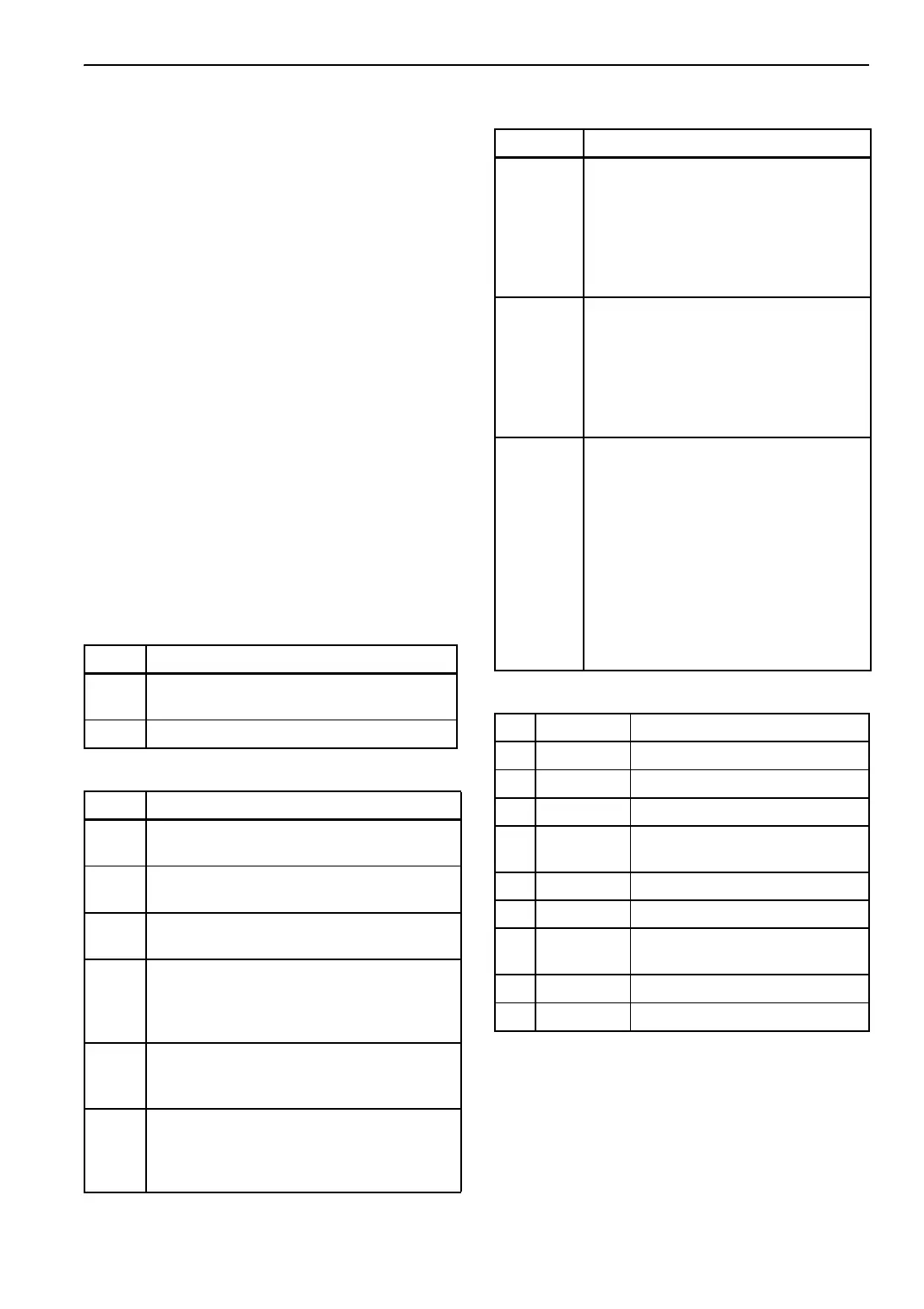
Power Connections
Input Description
8 Nominal 12-24 volt DC power to the phase
detect module.
CH Chassis ground
Inputs
Input Description
L1 This brown wire supplies standby power L1
to the phase detect module.
L2 This blue wire supplies standby power L2 to
the phase detect module.
L3 This black wire supplies standby power L3
to the phase detect module.
7EA If grounded, then outputs 7EB and 7EC are
grounding circuits. If 12-24 volts DC is
supplied, then outputs 7EB and 7EC will be
at 12-24 volts DC
SP If this wire is connected to chassis ground
the module will operate in single-phase
mode.
SP-GR
ND
This is an internal ground for the module. If
SP-GRND is jumpered to SP then the
module will be set to operate on single
phase.
Outputs
Output Description
7EB If phase rotation is L1, L2, L3 then this
wire will provide either a chassis ground
or 12-24 volts DC to energize the
appropriate phase rotation contactor.
The 7EC wire is interlocked to prevent
both phase contactors from being
energized at once.
7EC If phase rotation is L1, L3, L2 then this
wire will provide either a chassis ground
or 12-24 volts DC to energize the
appropriate phase rotation contactor.
The 7EB wire is interlocked to prevent
both phase contactors from being
energized at once.
ER This wire will output 12-24 volts DC 2 to
4 seconds after the voltage rises above
180 volts AC and all three phases are
present. If the voltage drops below 160
volts AC or a phase is lost and the
condition remains for 8 to 10 seconds,
the output is turned off. The module
continues to monitor and will again
output 12-24 volts DC 2 to 4 seconds
after the power returns to normal
(voltage rises above 180 volts AC and
all three phases are present).
Connector Pinout
Pin Wire Description
1 8 Power to Module
2 CH Chassis ground
3ER AC Power OK
4 7EA Power or ground input for 7EB or
7EC output
5 7EB Phase A-B-C
6 7EC Phase A-C-B
7 SP-GRND Internal ground to enable a
jumper circuit for SP logic
8 SP Grounded for single phase mode
9 Unused
 Loading...