4-6
4
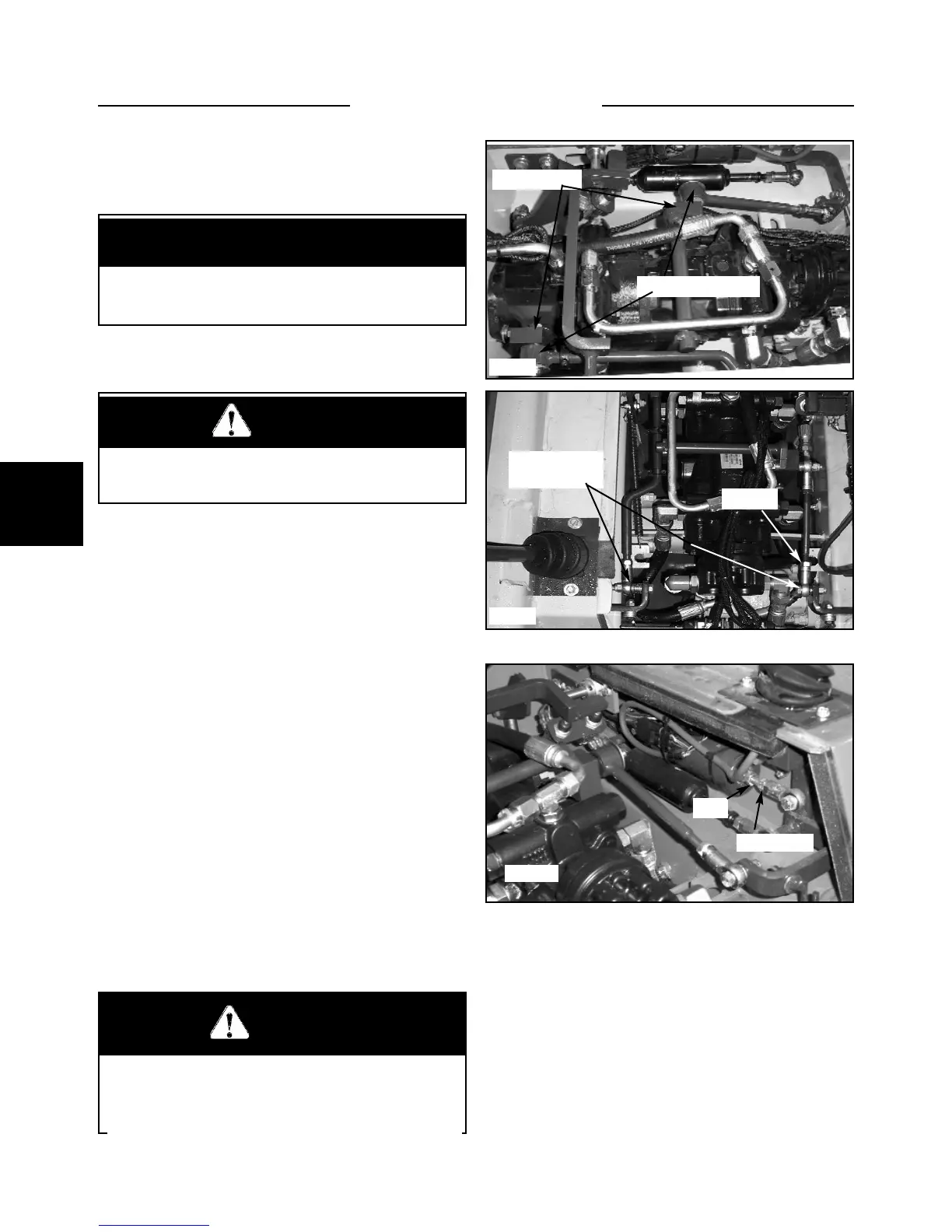
12 Note the location of the steering control linkage. (fig.
C5084, 5081)
13 Check the control rod end bushings for wear (fig.
5084). If any play is present between the bushings and the
bolts replace the rod ends.
14 Check the pintle levers for tightness on the swash
plate shaft. Tighten the clamping bolts or replace the pin-
tle lever if required. (fig. C5084)
15 If and when all rod bushings and pivot points have
been check for wear or binding, proceed with the neutral
adjustment.
16 Start the engine and release the parking brake. Cycle
the control levers through forward and reverse.
17 If the wheels are turning, remove the control rod
from the lever base (fig. C5622), loosen the jam nut and
adjust the rod end in or out to find neutral. Repeat for the
other side. Tighten the rod ends to levers and the jam
nuts against the rod ends and recheck the neutral adjust-
ment. Always ensure that the control rod has 1/2” thread
engagement into the rod end .
18 Very fine adjustment can be made at the hydro back
threaded rod. Adjustment here affects the control lever
angle. Loosen the jam nut and turn the hydroback rod in
or out to find a precise neutral.(fig. C5015) Tighten the
jam nut and recheck for neutral. Repeat if required. Only
make minor adjustments using this method.
19 Replace the seat and hydrostatic shield.
Neutral Adjustment
IMPORTANT
If you are unfamiliar with the control operations of
the loader, read the Owner’s / Operator’s Manual
beforehand.
Before performing the neutral adjustment make sure
the hydro back is functioning and adjusted properly.
Refer to page 4-5.
WARNING
Never work under the boom arms without the boom
supports engaged.
WARNING
Repairs or adjustment to the control lever system
may change the loader neutral position. Make sure
the loader is raised securely off the ground before
restarting the engine.
STEERING 4.1
C5622
C5084
C5015
Pintle levers
Rod end bushings
Control rod
end to lever
Jam nut
Jam nut
Rod