4-12
4
Angle Adjustment 85
After changing the control cable the foot pedal angle will
need to be verified and / or adjusted to provide operator
comfort and proper pedal travel clearance.
Note: If the operator feels discomfort due to current pedal
angles, they may be adjusted to their preference. Be sure
to check for pedal travel clearance afterward. Always
maintain a minimum of 3/8’’ (6mm) of thread into the
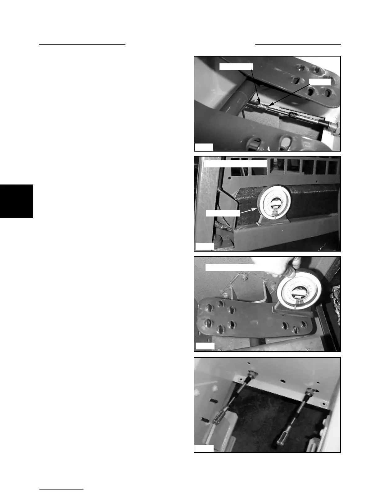
eyelet ends. (fig. C5098)
1 Make sure the clevis ends are screwed into the cable
threads a minimum of 3/8’’ (6mm). (fig. C5098)
2 Place an angle finder on the inner fender of the
loader to find the base measurement. Note the reading.
(fig. C2048)
4 Adjust the pedal angles by turning the clevis end on
the cable and by adjusting the mount nuts.(fig. C5086).
Adjust the lift and tilt pedal angle to 13º. Be sure to
allow for the base angle measurement taken previously.
Example: If the base angle measured 3º, add or subtract
that angle from the angle measured on the pedal.
5 Check the operation by cycling the pedals. Operation
should be smooth and the pedal should have unrestricted
travel when heeled and toed. If binding is occurring the
control valve spools or electric lock system may need ser-
vicing.
3 Place the angle finder on the heel of the pedal to be
checked or adjusted. (fig. C2050) Note the reading.
FOOT PEDALS 4.2
C5098
C2048
C5086
C2050
Jam nut
Cable clevis
Angle finder
Checking the pedal angle
Checking the base angle