4-5
4
Neutral Adjustment (con’t.)
IMPORTANT
Repairs or adjustment to the control lever system
may change the loader neutral position. Make sure
the loader is raised securely off the ground before
restarting the engine.
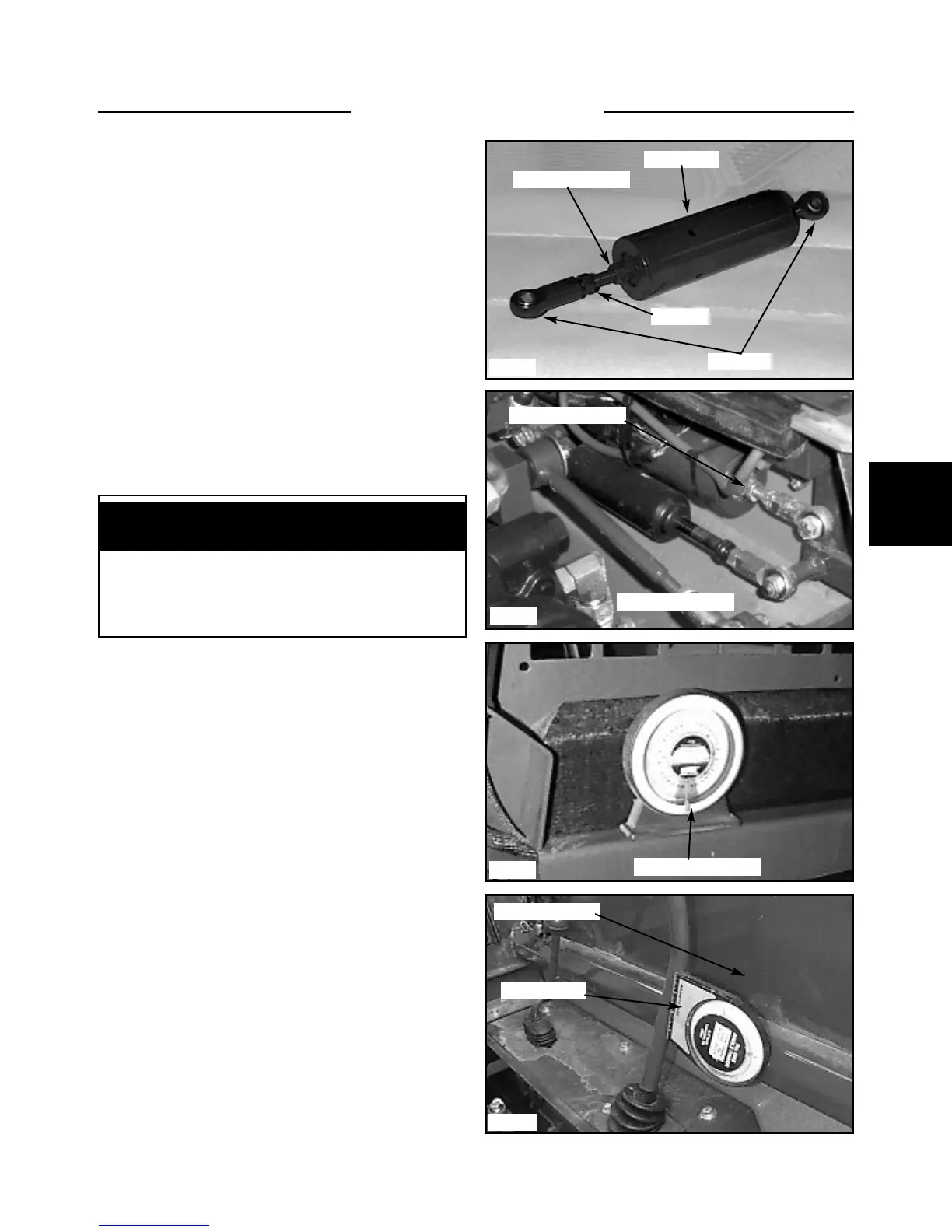
6 Loosen the 2 jam nuts next to the main body. (fig.
C1638, 5015)
7 Turn the 2 nuts away from the main body of the
hydroback.
8 Cycle the control lever several times.
9 Push the control lever rearward until you feel resis-
tance. Stop.
10 Turn the 2 jam nuts back toward the main body of
the hydroback until the nut just touches the flat washer.
11 Cycle the control lever again checking for a positive
feel. If you now have a positive neutral, tighten the 2 jam
nuts together and proceed to step 12, pg. 4-6. If the
hydroback still does not center, the hydroback has inter-
nal damage or wear. Replace the hydroback assembly
with a new one.
Hydro Back Replacement
Replacing the hydroback changes the steering control
lever angle and the neutral position. To correctly set the
angle after the hydro back has been installed:
1 Replace the hydroback by removing the 2 bolts locat-
ed at either end of the hydro back assembly.
2 Install the hydroback in the reverse order. Check the
steering control rod ends and replace them now if they
are worn.
3 Use an angle finder to check the base measurement
angle the loader is sitting at. (fig. C2048) Note the angle
the loader is sitting at. This measurement will have to be
added or subtracted to the next measurement to give the
most accurate adjustment.
4 Attach an angle finder to the most vertical part of the
control lever. (fig. C2442)
5 Turn the hydroback threaded rod (fig. C5015) in or
out of the female rod end to move the control lever to a
reading of 12º leaning forward. Be sure to allow for
angle the loader is sitting at. (Base angle) Jam the nut
against the rod end when completed.
Make sure there is a minimum of 3/8’’ (6mm) of thread
holding the female rod end to the threaded rod.
6. Proceed to neutral adjustments, step 12, pg. 4-6.
STEERING 4.1
C1638
C5015
C2442
C2048
Jam nut
2 Detent jam nuts
Hydroback
Rod ends
2 Detent jam nuts
Angle adjustment
Note the base angle
Angle finder
Lean forward 9°