4-16
4
Control Lever Replacement
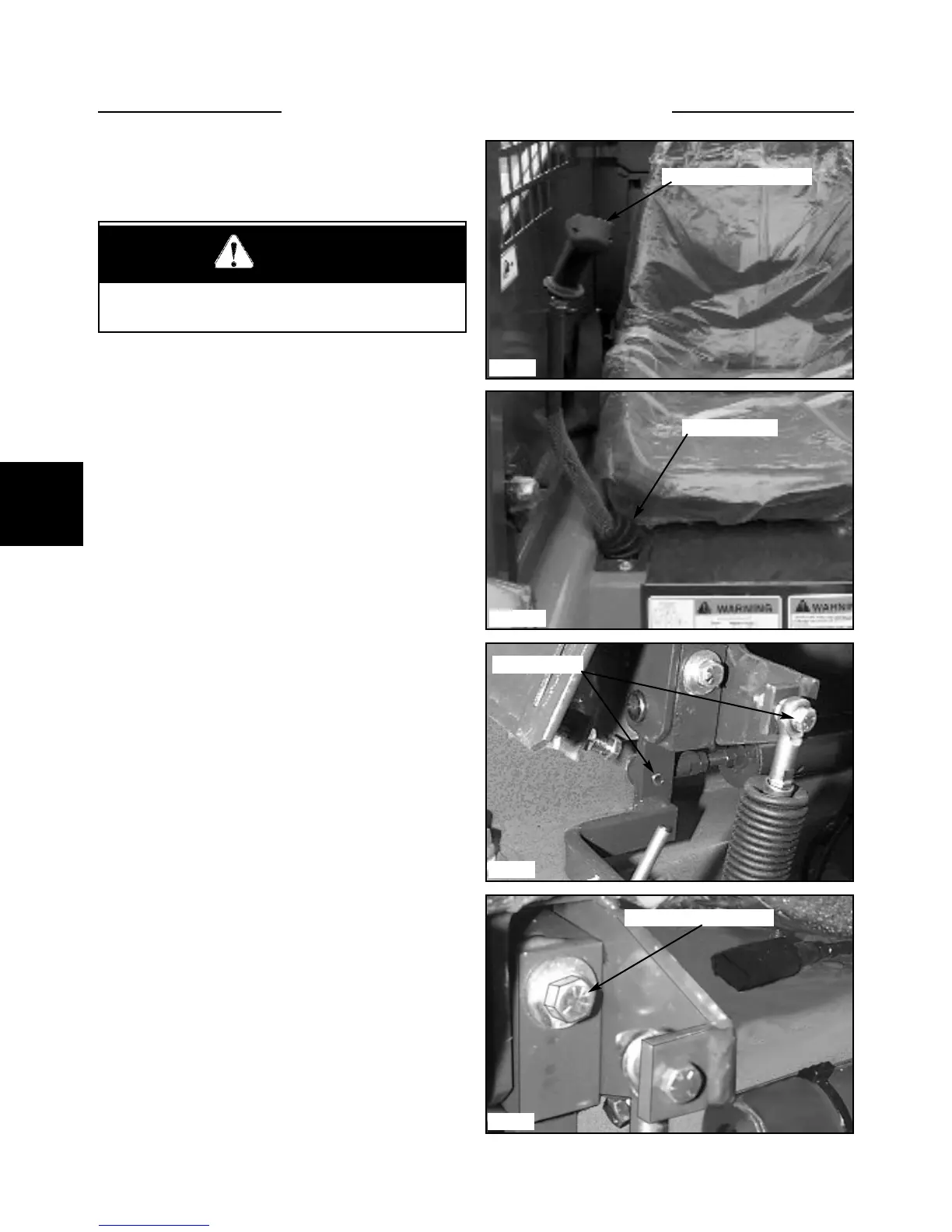
1 Raise the boom arms, engage the boom supports and
shut off the engine.
2 Remove the seat.
3 Remove the control handle from the steering lever by
removing the retaining bolt and dis-connecting the handle
transfer rod. (fig. C5017) The handle may be reused on
the new or repaired control lever.
4 Remove the bellows cover screws (fig.C5017a) and
remove the bellows.
5 Remove the bolt from the control rod linkage to the
control lever assembly. ( fig. C2447 )
6 Remove the mounting bolt from the control lever and
remove the control lever assembly. (fig. C2047)
Note: If the loader is equipped with optional electrical
accessories operated by control handle mounted switches,
the control handle switch wiring will need to be discon-
nected and transferred to the new steering lever.
If the control lever functions are sloppy due to excessive
wear of the swivel bushing, the swivel assembly may be
replaced.
See fig. C3274 page 4-14 for exploded view of control
lever assembly.
7 Save any spacer washers that may have been used.
8 Replace the control lever assembly.
Replace all parts in the reverse order. Use the spacer
washers to remove the movement of the steering lever.
Cycle the control lever after installation to check for
binding and travel clearance.
Check the control lever angles. Page 4-19.
Check the wheel speed, or tracking, to assure optimum
performance. Page 4-8.
WARNING
Never work under the boom arms without the boom
supports engaged.
HAND CONTROLS 4.3
C5017
C5017a
C2447
C2047
Bellows cover
Remove control handle
Remove bolts
Remove mounting bolt