5
5-11
ENGINE GLOW PLUGS 5.5
Before performing any test on the glow plugs, disconnect
the ground wire from the battery.
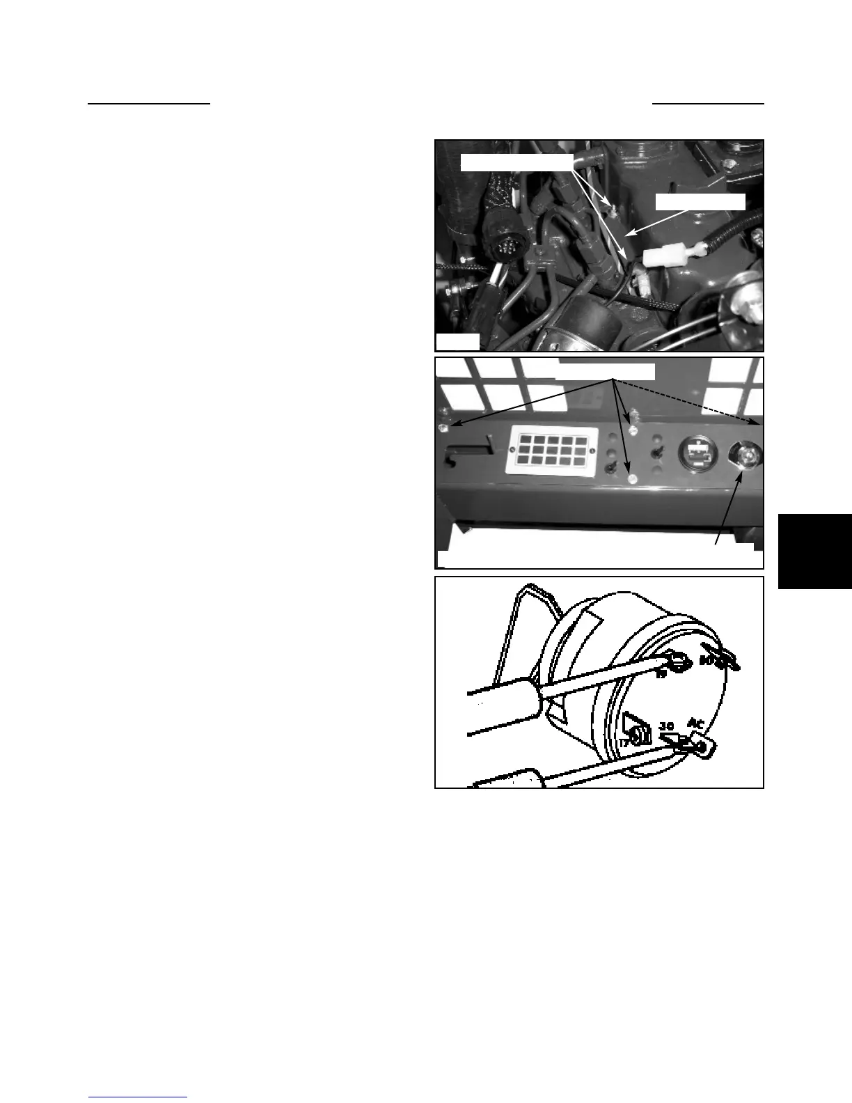
TEST 1: GLOW PLUGS.
With the ignition switch off, connect one end of the ohm-
meter lead to the manifold heater terminal and the other
lead end to a clean ground.(fig. C5092)
A reading of 1.5 ohms is normal.
An infinite or 0 reading means the heater is defective.
TEST 2: IGNITION SWITCH to GLOW PLUGS.
Remove the 6 screws retaining the dash panel to the
ROPS (fig. C5088) With the ignition switch off, discon-
nect the red / white wire from ignition terminal 19.
Connect one ohmmeter lead to the terminal marked 19 on
the ignition switch and the other lead to the red / white
wire.
Low to 0 reading means good continuity.
High reading means the red / white wire from the ignition
switch to the manifold heater is defective.
TEST 3 IGNITION SWITCH “HEAT” POSITION.
Connect the ohmmeter leads between the terminals
marked 30 and 19 on the ignition switch. (fig. C300) Turn
the ignition switch to the “HEAT” position and observe
the ohmmeter readings.
Low resistance reading normal.
High resistance reading, replace the ignition switch.
Testing the Glow Plugs
Pre-Heat Indicator
Check the ignition switch terminals 17 and 19 with an
ohmmeter. If there is good continuity between the two
terminals the bulb or wiring is bad on the pre-heat indi-
cator light.
To change the indicator bulb, remove the 6 screws retain-
ing the left hand dash panel to the dash pod. Select the
proper bulb, twist and pull the bulb from the dash panel.
Disconnect the wires and replace the bulb in reverse
order.
C5092
C5088
C300
Glow plug location
Connecting bar
Ignition switch
Mounting screws