4-15
4
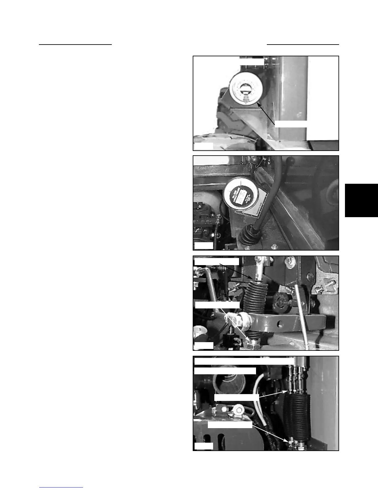
Angle Adjustment
After changing the control cable the control lever angle
will need to be verified and / or adjusted to provide oper-
ator comfort and proper travel clearance.
1 Make sure the rod ends are screwed onto the rod
threads a minimum of 3/8’’ (6mm).
2 Place an angle finder on the front shield of the
loader to find the base measurement. Note the reading.
(fig. C2049)
3 Place the angle finder on the control lever as shown
in (fig. C2449). Note the reading. The correct angle is 8º
+ / - 1º.
4 Adjust the angle by adjusting the cable mount nuts to
move the cable up or down on its mount. (fig. C2448) Be
sure to allow for the base angle, the angle the loader may
be leaning at while measuring. Add or subtract this mea-
surement as necessary.
5 If you are not able to achieve proper control lever
angle, adjustment of cable mount nuts at the valve may be
required. Also the cable end at the lever may need to be
adjusted in or out.
6 Cycle the control levers to check for travel clearance.
7 Replace the seat and hydrostatic shields.
HAND CONTROLS 4.3
C2367
C2448
C2449
C2049
Valve end of cable view
Tighten jam nuts
Adjust cable nuts
Checking the base angle
Angle finder
Tighten jam nuts
Adjust cable nuts
Not exactly as shown on some loaders