1
CONTROL VALVE 1.3
Testing and Adjusting the Relief Valve Pressure
Hoses and gauges required for this test must be capable
of withstanding 3000 psi (207 bar) continuous pressure,
and hydraulic flow meter capable of measuring 30 gallons
per minute. (113 l/min) (fig. C5004) This test also
checks the status of the gear pump capacities.
Pressure fluctuations may be caused by restricted oil flow
through the relief valve. The relief valve may need
replacing when its filter is contaminated.
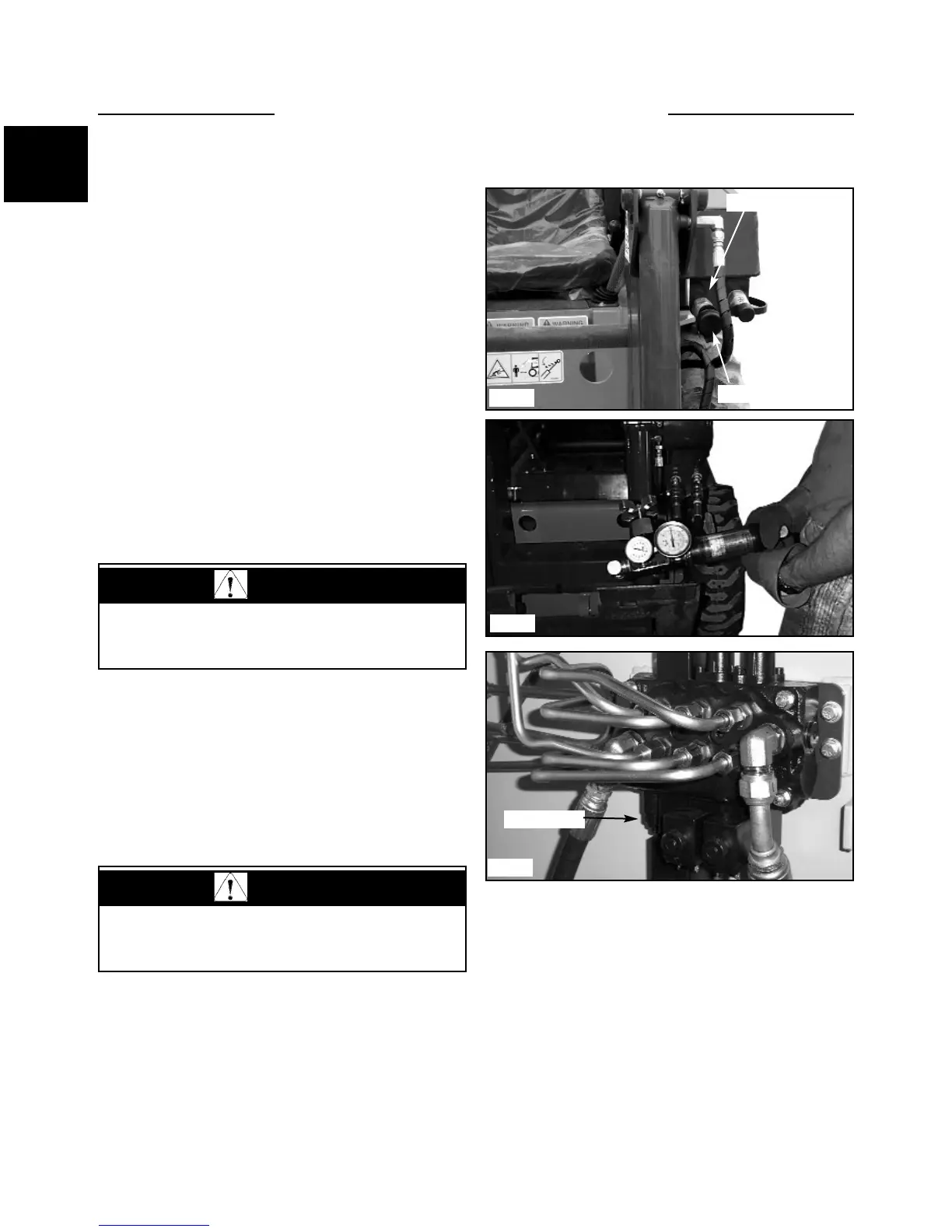
1 Install the flow meter / pressure tester to the auxiliary
hydraulic quick couplers. The female coupler attached to
the loader provides the power out when the auxiliary
control is engaged. (fig, C5004) Connect the flow meter
and pressure gauge inlet side to match the power out of
the female auxiliary coupler to prevent meter and gauge
damage. Be sure to connect a return line to the male
auxiliary hydraulic quick coupler. (fig. C2352)
2 Start the engine and engage the auxiliary hydraulic
system. Increase the engine speed to full operating rpm.
(See Section 7 for checking and adjusting engine speed to
3000 rpm plus or minus 25 rpm)
3 Turn the flow control valve on the flow meter to
restrict the oil flow down to 2 gal /min. (7.5 l/min ) As
you are turning the flow control valve, watch the pressure
gauge and make sure it does not go over 3000 psi (207
bar). Stop further adjustment immediately if the reading
goes over this setting. Shut off the auxiliary hydraulic
system and shut off the engine. Move to step 6 to make
initial setting.
1-10
WARNING
To prevent personal injury or damage to the loader,
do not adjust the relief valve while the engine is
operating.
CAUTION
Adjusting the relief valve setting too high may cause
damage to the gear pump.
C5004
Auxiliary couplers
Pressure out
C2352
C5063
Relief valve