1
1-11
4 Repeat steps 2 and 3 if necessary. Allow the loader to
operate at this setting until the oil temperature has
increased to 160° F (71ºC), operating temperature.
5 Turn the flow control valve further to restrict the oil
flow to no flow. (Zero) Correct pressure setting is 2100
psi +/- 100 psi (148 bar +/- 6.9 bar).
6 If adjustment is necessary, return the flow control
valve to the open position, shut down the auxiliary
hydraulic system and shut off the engine. Locate the
control valve in the engine compartment.
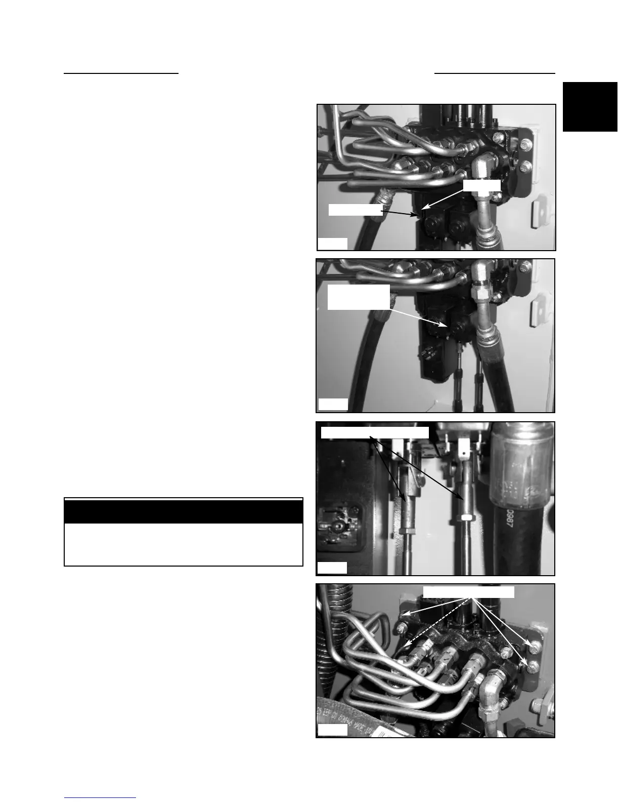
7 Loosen the jam nut on the relief valve adjusting
screw and turn the screw clockwise, counting the turns,
until the screw bottoms out. (fig. C5063)
8 Turn the screw back. Reduce the number of turns
that you turned in to increase the pressure, increase the
number of turns to decrease the pressure.
9 Retake the pressure readings by performing steps 2
through 5. If necessary make further adjustments by
repeating steps 6 through 9.
NOTE: If adequate pressure and / or flow is not
available, the gear pump could be failing, the intake to
the gear pump is restricted, or the filter in the relief
valve is clogged.
Control Valve Replacement
1 Remove any attachment and shut off the engine.
Turn the key on with the safety devices activated so the
pedals can be moved. Slowly jog both pedals and press
the electric auxiliary switch. This will take any pressure
out of the system.
2 Disconnect the control cables, electrical solenoid
spool locks, and electrical auxiliary solenoid wiring
connectors if equipped. (fig. C5064, C5065)
3 Disconnect the the inlet hose coming from the gear
pump. Cap the hose and fitting and remove the adapter
fitting in the control valve.
4 Disconnect the 6 hoses going to the boom, bucket
and auxiliary circuits. Marking the hoses as you remove
them is recommended to ease re-assembly and assure the
circuits are functioning properly at restart.(fig. C5005)
5 Disconnect the accumulator line from the electric
auxiliary circuit and remove the adapter fitting( if so
equipped). Plug and cap all open ports and hose ends.
CONTROL VALVE 1.3
Clean the work area prior to repair. Cap all open
lines, fittings and ports to prevent contamination.
IMPORTANT
C5005
C5063
Jam nut
Relief valve
C5064
C5065
Solenoid coil
mounting nuts
Control valve mounts
Disconnect control cables