6-5
6
QUICK - TACH 6.1
Disassembly
Follow the exploded schematic on the 2nd page of this
section to assist in taking apart the locking mechanism,
and to assemble the system back together. Please note that
the quick - tach does not have to be removed to service or
replace locking mechanism parts.
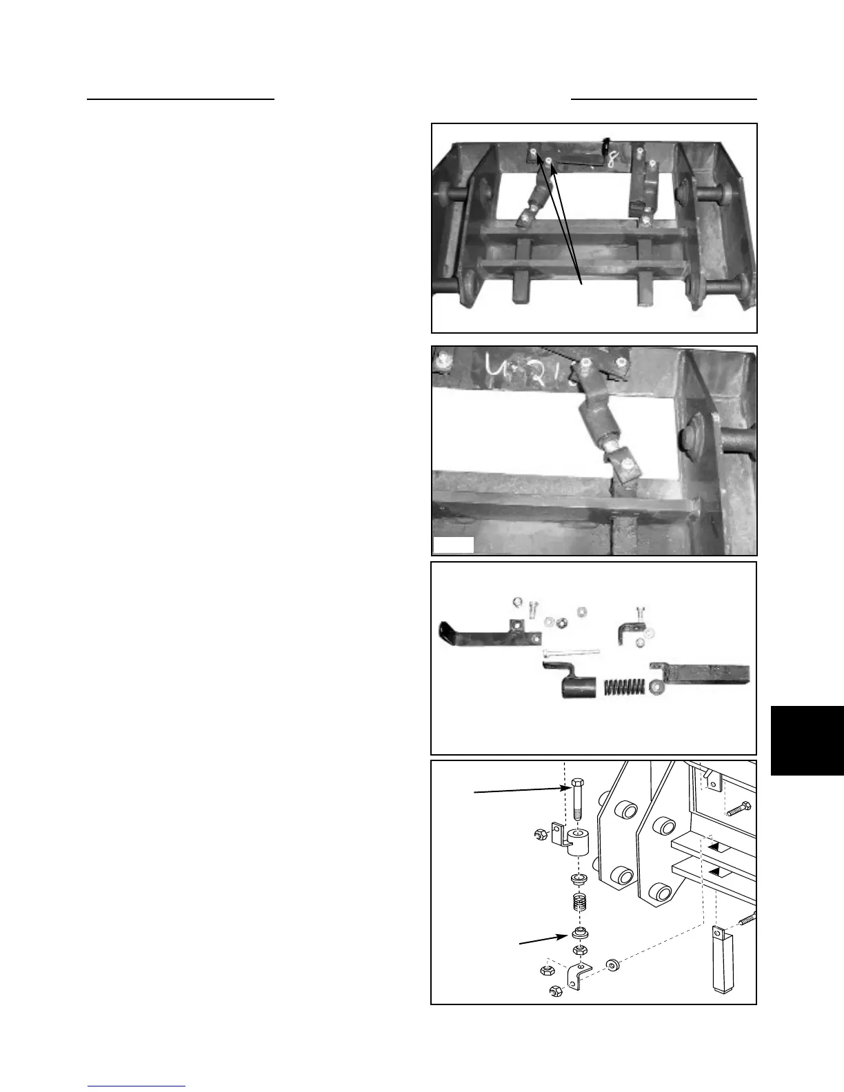
1 Remove the bolt retaining the lock handle to the lock
linkage. (fig. C5292)
2 Remove the bolt retaining the lock handle to the
quick - tach frame. (fig. C5292)
3 Pull the locking pin and linkage out of the guide
bushing. (fig. C5293)
4 Remove the spring assembly from the pin hinge.
5 Separate the parts and inspect the spring for broken
or sacking (compressed) coils. (fig. C5294) Replace parts
as required.
6 Inspect the locking pin for wear. Make sure the end
of the pin is not worn or broken off. Check the fit of the
pin in the quick - tach guides. If the pin or the guides are
excessively worn replace the pin or complete quick - tach
assembly.
7 Inspect the lock handle mounting holes for fit.
Replace the handles or bolts as required if the fit is slop-
py. (fig. C5294)
8 Check the fit of the lower pivot pins in the quick -
tach. Discard worn pins and replace the hardened bush-
ings in the quick - tach if so equipped.
9 Check and replace any grease fittings that are dam-
aged or defective.
Assembly
Upon assembling the locking mechanism to the quick -
tach, use 242 Loctite (blue) on all the mounting nuts and
bolts.
1 When assembling the spring in to the spring housing,
tighten the nut to obtain a length of 2-3/8”. This is mea-
sured from under the head of the bolt to the bottom of the
spring collar. (fig. C2513) This is very crucial for lock
pin engagement to the attachment.
2 Replace the rest of the lock mechanism in the reverse
order above.
3 Lubricate all pins and bushings.
4 Check the lock mechanism by cycling the lock levers
to ensure correct engagement through the attachment and
sufficient pressure to hold the lock system down in the
over - center position. (Engages and stays in the locked
position)
C5292
C5293
C5294
Q/T handle bolts
C2513
Bolt
Bottom
spring collar