5
5-14
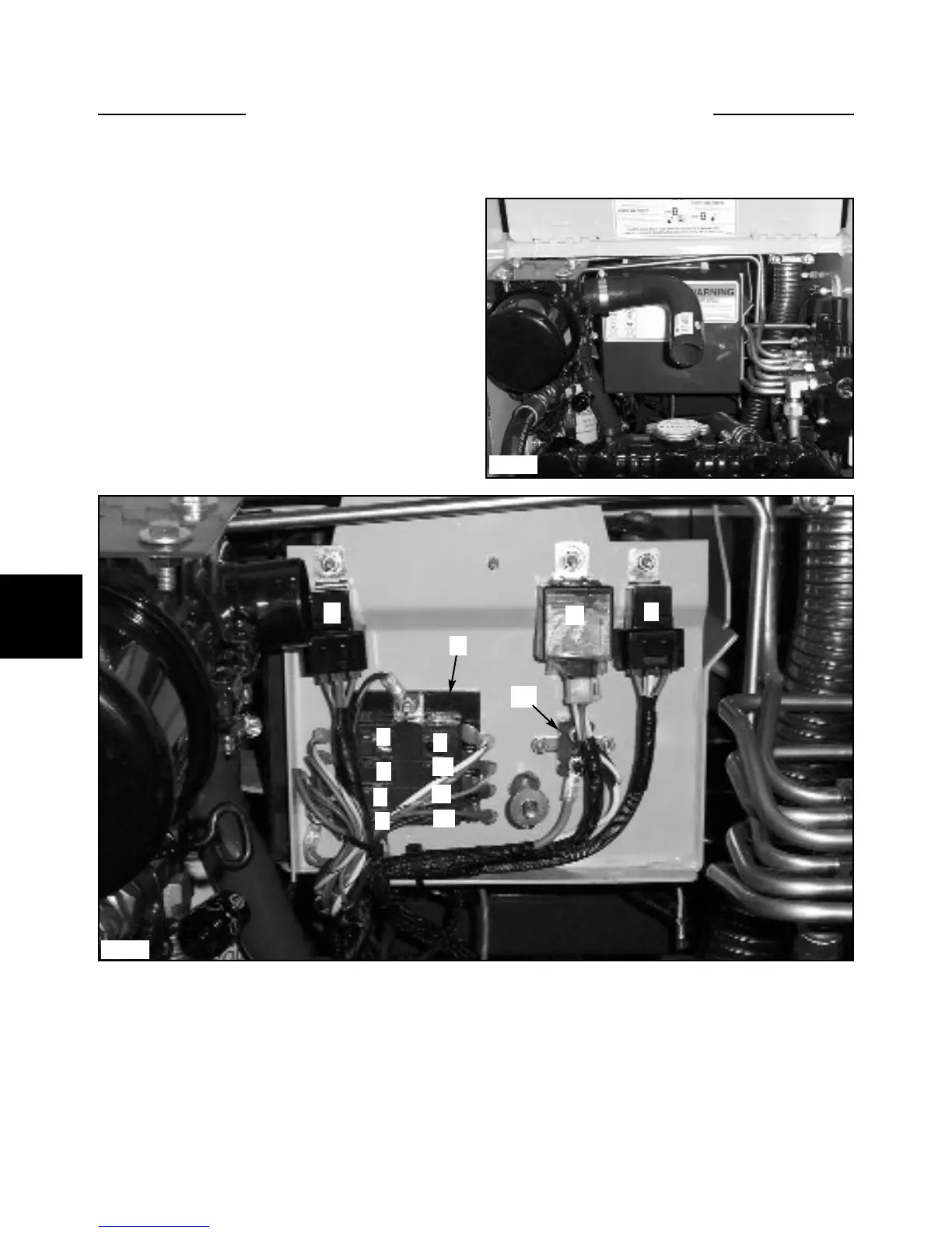
ELECTRICAL PANEL 5.7
The loader is equipped with a 12 volt, negative ground
electrical system. The fuse and relay panels are located in
the engine compartment, attached to the back of the bat-
tery box, over the engine cover. (fig. C5214)
To access the electrical panel:
1 Open the rear door and raise the engine cover.
2 Remove the knob holding the electrical panel cover
closed. (fig. C5214)
3 Open the cover and all fuses and relays will be
exposed. (fig. C5102)
Visually check the fuses for burnt contacts.
The ground bolt should be checked occasionally for cor-
rosion and cleaned if necessary. Use a dielectric grease to
protect the ground point from the elements.
7 Electric Auxiliary Fuse
8 Spare Fuse
9 Starter(W/B), Glow Plug Fuse (R/W)
10 Valve Locks Fuse(Or/W)
11 Horn Fuse
12 Spare Fuse
13 Circuit Breaker, 30 amp.
ELECTRICAL PANEL LEGEND.(fig. C2052)
1 Glow plug Relay
2 Starter Relay
3 Engine Fuel Stop Timer
4 Fuse Panel
5 Stop Timer Fuse (Y/B)
6 Alternator Fuse (B/W)
C5102
C5214
3
21
4
5
6
7
8
9
10
11
12
13