5
WIRING SCHEMATIC 5.2
PIN WIRE COLOR FUNCTION
1 Purple Eng. Oil pressure sender
2 Orn / Blue Fuel level sender
3 Grey Alternator
4 Grey / Wht Brake switch to light
5 Blue Hyd. oil temp. switch
6 Yl / Red Spare
7 Wht / Brn Button to horn
8 Brown Aux. solenoid
9 Wht / Ppl Spare
10 Red Seat belt switch
11 Tan Starter relay
12 Red / Wht Glow plug relay
13 Pple / Wht Engine water temp. sender
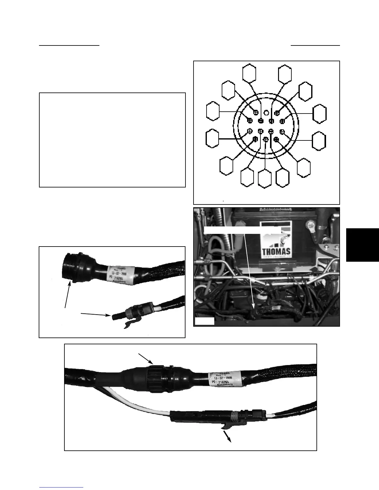
ROPS Harness Connector
Diagram C2459 Legend. Shown is the wire color and
function of each pin terminal in the connector plug.
The photographs below and at right show the actual
ROPS harness plug connection. This is a view with the
seat removed and the battery access panel removed.
To separate the main electrical harness connection, push
the locking tab in the direction of the arrow (fig. 5316)
and twist the collar clockwise to release.
5-3
C2459
C5634
C5273
C5635
Main harness plug connection
1
2
3
4
5
6
7
8
9
10
11
12
13
ROPS harness
connectors
Twist
Push tab down to unliock