1
1-15
Remove the hydraulic control valve as outlined in the
removal section, page 1-7. Ensure all openings are
plugged to prevent solvents and dirt from contaminating
the control valve assembly. Before disassembling the
hydraulic control valve, clean the body with a suitable
solvent and dry with compressed air.
Refer to diagram C3287, pg. 1-13 to assist in the
disassembly of the control valve.
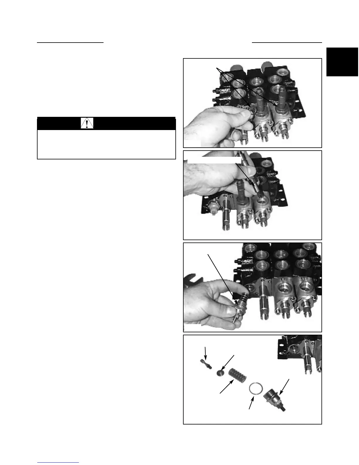
1. Remove the solenoid coils and O-ring seals. (fig.
C2368).
2. Remove the locking pin assembly from adapter
block. (fig. C2369)
3. Remove the pressure relief valve. (fig. C2370) Tip
the valve down slightly to ensure the valve poppet comes
out with the spring
Note: Figure C5179 shows an exploded view of the
relief valve system.
Disassembly / Repair 85
CONTROL VALVE 1.3
WARNING
To avoid eye injury, use safety goggles when
cleaning with compressed air.
C2368
O-ring seals
C2369
Locking pin assembly
C2370
C5179
Relief valve assembly
Sealing washer
Spring
Cap
Valve poppet
Poppet