2-25
2
DRIVE MOTOR 2.12
Removal
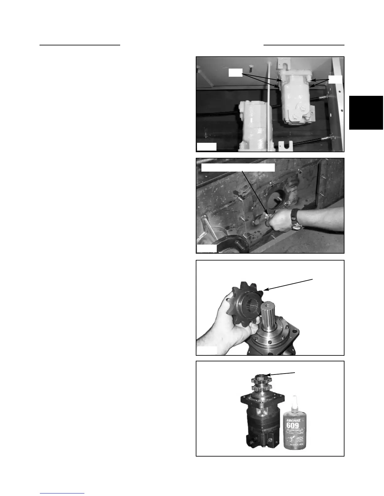
12 Remove the jam nuts, mounting nuts and lock wash-
ers from the 4 mounting bolts retaining the drive motor to
the final drive housing. (fig. C5115) Hold the head of the
bolts from inside the final drive housing. (fig. C5075)
13 Remove the drive motor. Seal the drive motor with
silicone upon reassembly.
14 Upon reassembly torque the 4 mounting nuts to 80 ft
lbs (110.4 N m).
15 If the drive motor replacement is being performed
because of major parts failure, such as geroler damage,
the hydraulic system must be checked for contamination
and flushed if necessary as outlined in Section 2.7.
17 Install the key, sprocket and nut. Apply Loctite 609
(blue) to the threads of the shaft before torquing (fig.
C5062) and torque the nut to 275 ft lbs. (373 Nm).
16 Remove the drive motor sprocket and bolt. Visually
inspect the drive motor sprocket. Check for worn or dam-
aged teeth on both the outside of the sprocket, and the
inside spline (fig. C2079).
C5115
Nuts
Nuts
C5075
C2079
C5062
Torque motor mounting bolt
Apply loctite
Not exactly as shown
Drive sprocket