Receiver Descrambler - User Manual (release 7.3.1)
Remotely, the unit’s status can be checked by using the web client and looking at the status icons on the top of
the main window. To see a detailed list of errors, click on the tab from the web client.
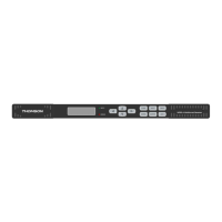
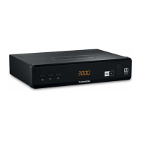
The INPUT LED indicates the presence of a stream at the user-selected input. “Stream present”
is represented by a green INPUT LED while “stream NOT present” is represented by a dark
INPUT LED.
The ERROR LED represents the combined status of the unit’s error indicators. If INPUT, TEMP,
or FAN status is in the error state, the LED will be red. If all error indicators are good, the LED
will be dark.
2.5 Input Error Logic
The input status is based on the selected input card’s status and the transport error indicator bit in the transport
stream being decoded. For example if the current input is VSB, the input status is based on: VSB receiver lock,
RF channel level, and the MER level. The RF channel and MER thresholds can be set by the user. If the unit
detects the presence of the transport error bit in a transport packet header, the input status will be an error for
0.5 seconds each time the TS error bit is set. The system must detect a constant cadence of sync bytes
(0x47h) every 188 bytes and detect a valid PAT at least every 500 ms in order for the INPUT LED to illuminate.
2.6 Temperature Error Logic
The temperature error indicator is based on the correct operation of the unit. If the unit’s internal temperature
exceeds 70 degrees C, the temperature status will be in the error state.
2.7 Fan Error Logic
If the fan in the unit fails, the fan status will be in the error state. The fan status will be good as long as the fan
is spinning at the proper RPM.
2.8 SNMP Traps
The unit contains separate SNMP Traps for Fan Status, Temperature Status, Input Status, and IP Receive
Group. Whenever any item changes state, a trap is sent to the configured host.
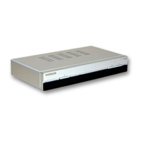
2.9 Input/Output Slot Organization
The unit’s modular design allows many different input/output configurations. An indexing system is used to
identify module slots for configuration and monitoring reference. The bottom row of slots is numbered 1-1
through 1-4 (left to right). The top row is numbered 2-1 through 2-4 as shown.