1.7 Operating elements at the rear panel
ITC500 / page 15
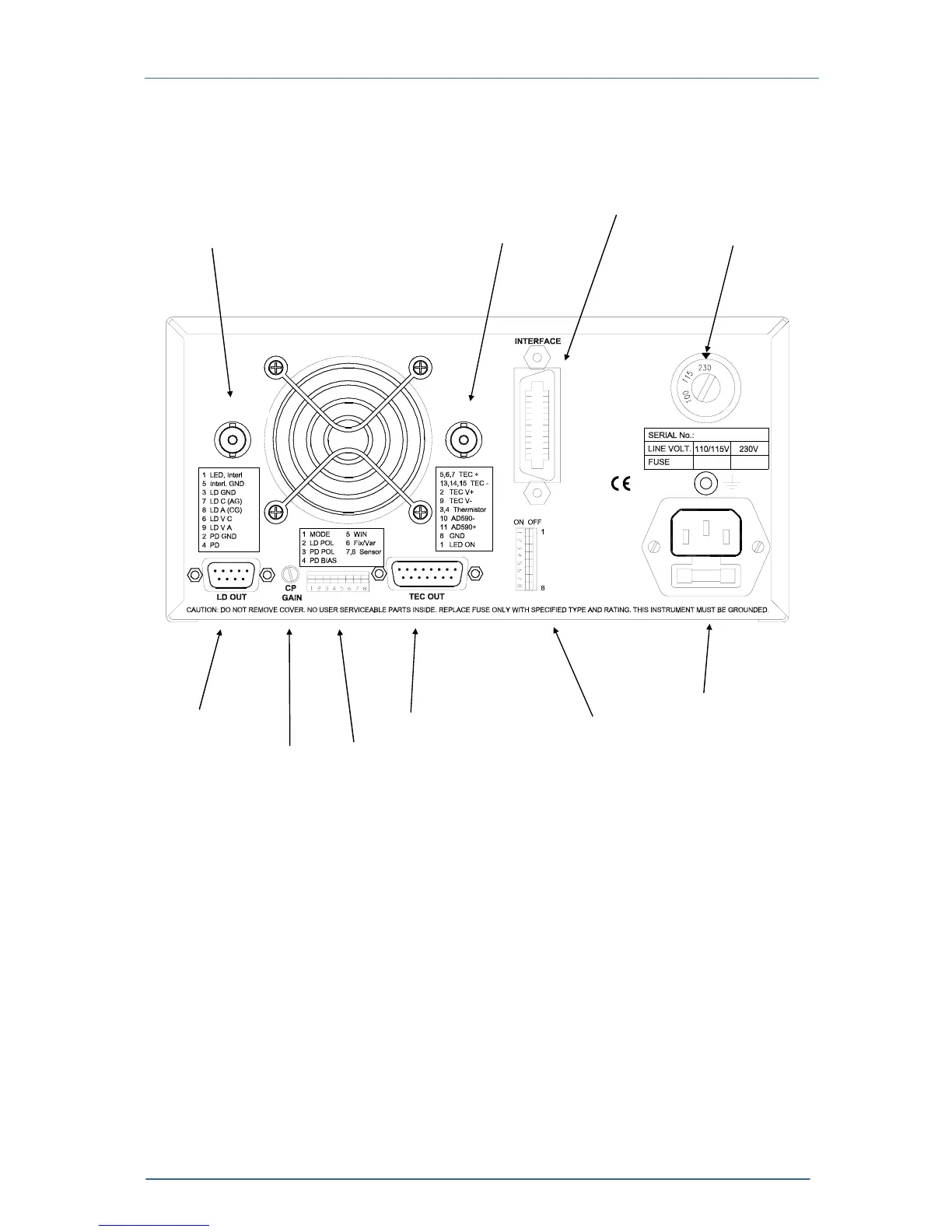
1.7 Operating elements at the rear panel
Interface jack
Temperature Tune input Analog temp. control output Mains voltage selector
Mains jack with fuse
Laser diode output TEC output DIP switch for interface configuration
CP gain DIP switch for „wake up“ preset
Figure 2 Operating elements at the rear panel
The rear panel of the combi controller ITC5xx contains the mains connector with
fuse, the output jacks (9/15pin D-SUB), the analog temperature control output, the
preset DIP switch bank and the PD gain control potentiometer.
If the ITC5xx is equipped with the IEEE488.2 there is an additional DIP switch bank
to set the IEEE 488 device address. You will also find the 24pin IEEE488 jack.
TEMP OUTAUX
TUNE IN