1.9 Connecting components
ITC500 / page 29
1.9.9 Connecting interlock and status LED
Interlock, cable damage monitoring
Pin 1 and pin 5 of the connector jack will serve as test connectors to determine
whether the current output for the laser diode may be switched on. Between the two
pins a low resistive (<100Ω) connection must be maintained. Also short-circuiting is
permitted. With the contacts open the current module cannot be switched on. Should
the contact open during operation the output will be switched off immediately.
Status LED
It is also possible to switch a LED with a 0.5 kΩ resistor in parallel between the two
pins. The LED will light up if the current output is switched on.
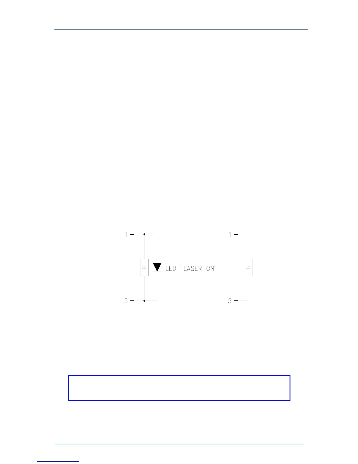
Here are the two possibilities for the pin assignment:
about 0.5 kΩ <100 Ω
Figure 11 Interlock and status LED
NOTE
A 0.5 kΩ- resistor without LED (or the LED is incorrectly poled) may lead
to malfunction as the status of the interlock is then undetermined.