FFS2000 Series Chapter 6: Fiber Preparation
Page 40 TTN047338-D02
Once the dunking jig has been raised, the vacuum will shut off, the ultrasonic cleaner will automatically turn on
and the Clean Right Indicator of the GUI will highlight red. The indicators will remain in this state for the
preset clean time.
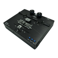
After the clean time has elapsed the ultrasonic cleaner will shut off, the right clean indicator lamp (see Figure 40)
on the splicer workstation will light red, and the Clean Right Indicator of the GUI will highlight green.
When the dunking jig is lowered, the Clean Right Indicator of the GUI will cease to be highlighted and the
red indicator lamp of the splicer workstation will turn off.
Note: The quickest, most convenient way to remove the FHB from the dunking jig, when in the dunked position, is
to grab the FHB and allow the dunking jig to “fall” back into place. If the FHB and dunking jig are first lowered
back together, the vacuum will activate and make removal of the FHB more difficult.
6.3.3. Diagnostics
Problem Possible Cause Solution
Vacuum won’t hold
fiber in FHB V-
grooves
FHB V-grooves are dirty. Clean the FHB V-grooves with the soft brush.
Obstruction present under
dunking jig
Make sure the area underneath the dunking jig is
free of dirt particles. If necessary clean the surface
with a mild soap.
Bad or missing O-ring on
undersurface of dunking jig
Contact Thorlabs for a replacement part.
6.4. Cleaving the Fiber
A Tension and Scribe method of cleaving is used to provide consistent, low end-angle cleaves.
6.4.1. Setting up
The appropriate parameters should be pre-loaded and may be accessed in the Fiber Preparation Menu in the
GUI.
Fiber Preparation Parameters
Check the parameters of the ‘Cleave Angle Limits’ and adjust as needed.
The Cleave Parameters determine the distance that the Cleave Blade moves towards the Fiber, before the
Cleave operation commences. This should already be setup for your workstation. Refer to the maintenance
section or contact Thorlabs if you require further advice on this.
Note: Parameter changes in the software interface are not saved into the configuration file (*.xml) until a file save
is executed.
6.4.2. Cleaving Procedure
Once the coating has been stripped, position the FHB at the right cleave station, just forward of the stripper slot.
When the FHB is properly seated, the vacuum will automatically activate. Make sure:
The cleave lever is in the forward position prior to seating.
The fiber lies properly in the cleave insert V-groove.
Move the cleave lever to the back position to apply tension to the fiber. The center, moving part of the FHB will
move away from the Cleave Block 1 to 2 mm, but should then stop. DO NOT continue with the Cleave operation if

 Loading...