FFS2000 Series Chapter 5: Software
Rev B, July 21, 2017 Page 23
5.9. Camera Image
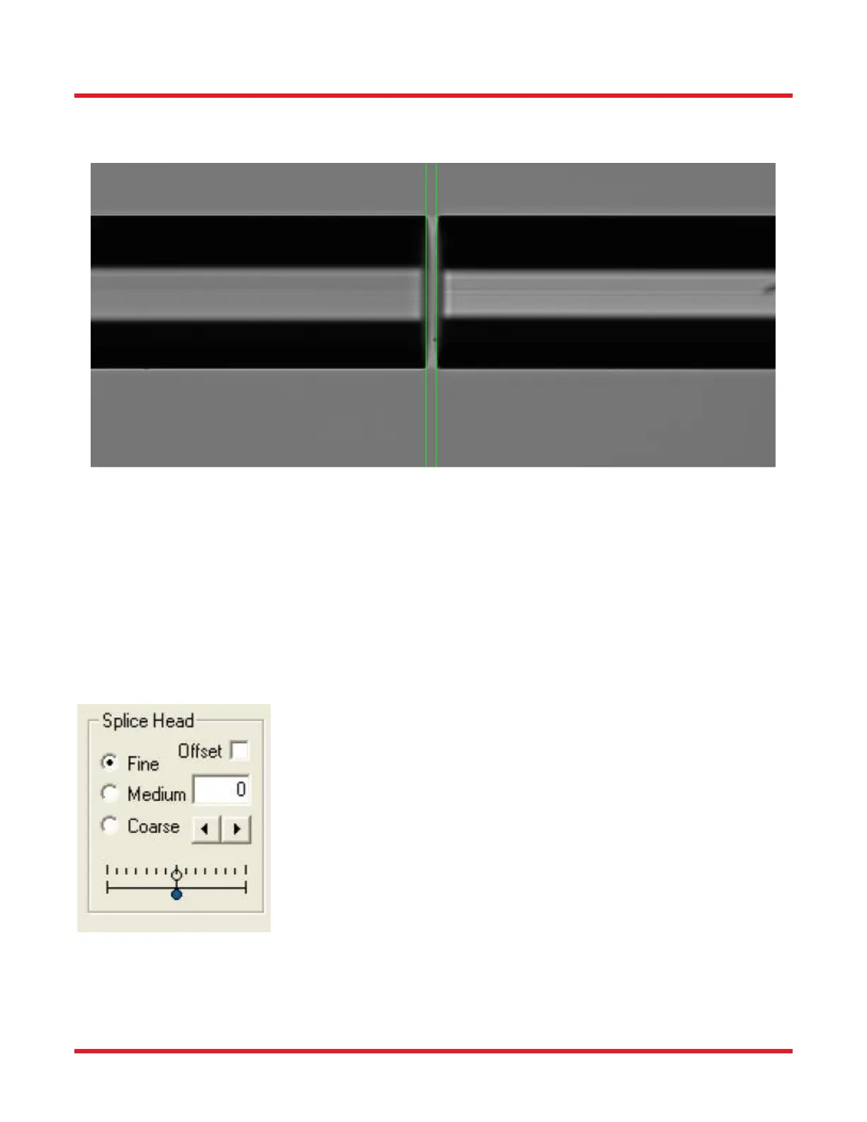
The camera image shown below is a side view (“Front” or “Back”) of a pair of fibers.
Figure 25 Example of a Side View
The pixels are compressed so that the entire image fits in the window. This becomes apparent when the end of a
fiber is imaged and appears elliptical rather than circular. To achieve square pixels and a 1:1 aspect ratio, right
click on the image area to activate the “Vertical Scrollbar” and the “Horizontal Scrollbar”.
5.10. Movement Control Bar
The seven boxes in the Movement Control Bar permit the user to move the fiber holding blocks and splice head at
will, by clicking on the forward and back arrows. The radio buttons labeled “Fine,” “Medium” and “Coarse” adjust
the magnitude of each step.
The “Splice Head” box enables the user to move the splice head left or right.
Positive motion is to the right and the position is displayed in microns.
 Loading...