FFS2000 Series Chapter 7: Splicing the Fiber
Rev B, July 21, 2017 Page 43
Chapter 7 Splicing the Fiber
7.1. Introduction
7.1.1. Filament Fusion
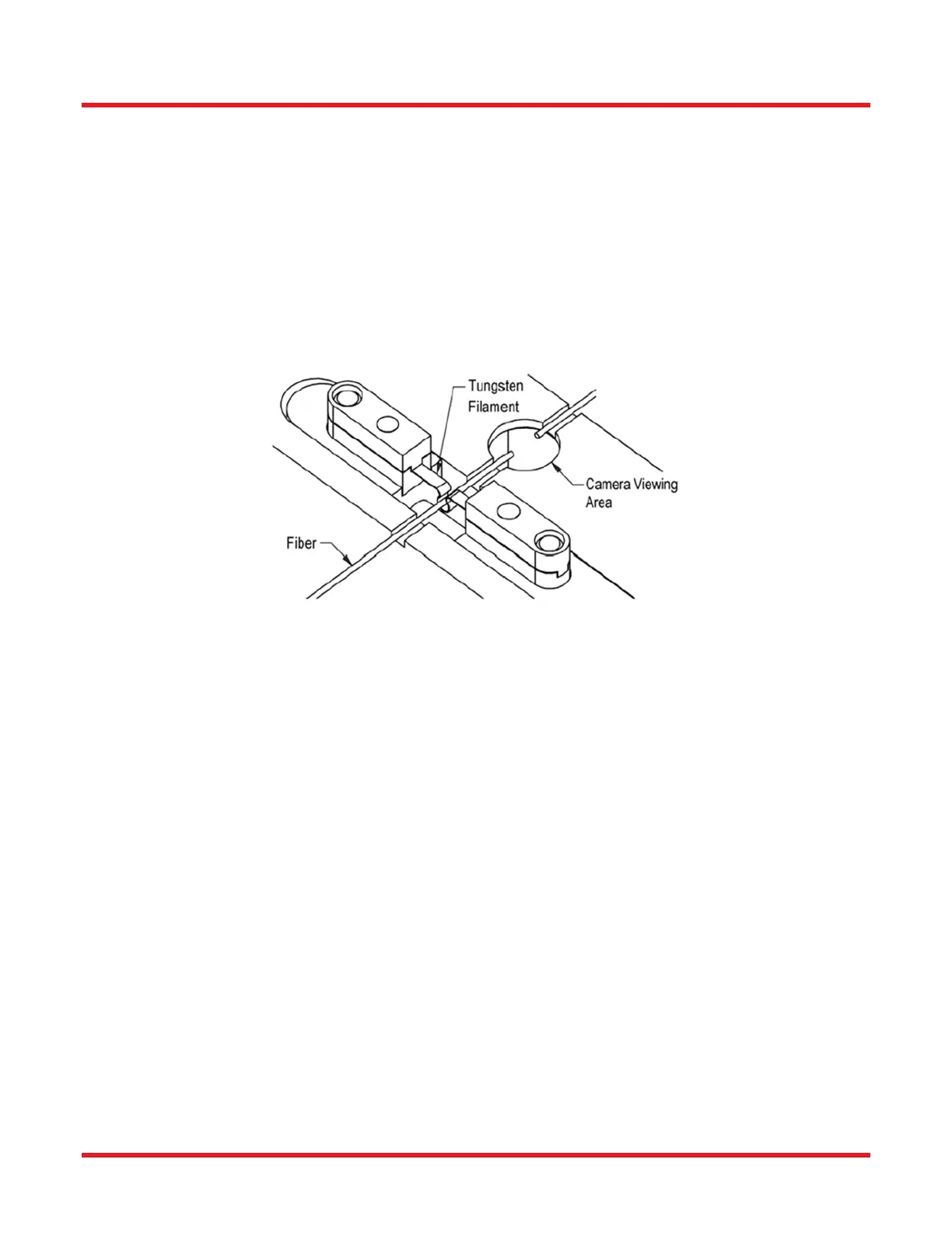
The FFS2000 Series uses a tungsten or iridium filament (sold separately) to provide the heat necessary to fuse
the fibers together. The filament is a thin tungsten or iridium ribbon shaped to form a loop that is open at the top
(see Figure 42). The FHBs are placed in the Transfer Jig at the splicing station with the fibers roughly positioned
in the center of the camera viewing area. Depending on the alignment method selected, the FFS3 software will
use inputs from the CCD camera and/or the external optical power meter or polarimeter to precisely align the
fibers. Computer-controlled stepper motors are used to position the fibers during alignment and to push the fibers
together during the filament fusion.
Figure 42 Splice Filament
After the software aligns the fibers, the splice head is repositioned, centering the filament under the fiber ends.
Power is applied to the filament to raise its temperature to a level hot enough to fuse the fibers together, typically
about 2600°C. Because the tungsten filament would oxidize (burn up) if brought up to such a high temperature in
air, an inert gas (argon) is used to purge the splice chamber of oxygen. In order to keep the fibers clean and
improve splice strength, the purging gas is set to flow over the fibers at a high rate during the fusion process. The
fiber ends are allowed to heat up before they are pushed together. This smoothes over any discontinuities in the
fiber ends and increases the plasticity of the glass. The hot fibers are pushed together, producing a smooth splice
while maintaining the precision alignment.
7.1.2. Fire Polish
When a fusion splice is made, silica will evaporate off of the hot center joint region of the splice and condense on
either side of the joint where the fiber is cooler. These condensed silica deposits, composed primarily of β-SiO
2
or
crystobalite, act as stress raisers (flaws) and if the splice is put under tension, the fiber will break at one of these
points. The purpose of the fire polishing process is to remove or minimize these deposits, and thereby improve
splice strength.
Fire polishing is performed immediately after the splice is complete, before the filament is turned off. The splice
head is quickly traversed back and forth along the length of the fiber, such that the hot filament passes over the
regions where the deposits have formed. This quick surface hot treatment reflows the existing deposits without
generating new concentrations.
7.2. Setting Up
During purchasing Thorlabs personnel will have advised on your application and configured Splice Files to suit.
Be sure to have the appropriate Splice File loaded for the fiber combination to be processed.
 Loading...