FFS2000 Series Chapter 7: Splicing the Fiber
Page 44 TTN047338-D02
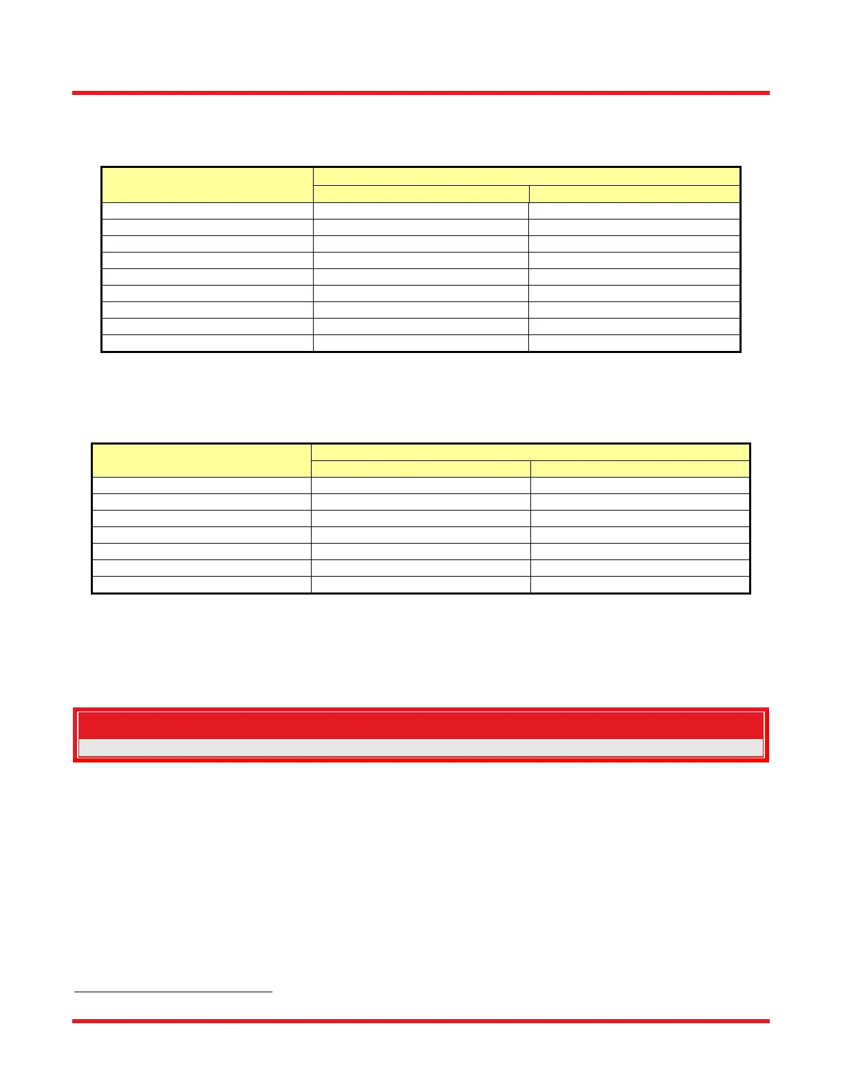
7.2.1. Splice Settings
Splice Parameters: Check the parameters of the ‘Splice Parameters’ in the ‘Splice’ menu of the GUI
under Splice Parameters. Refer to the table below for typical values.
Parameter Fiber Diameter
80 µm 125 µm
Pre-Gap
8 µm 8 µm
Pre-Push
5 µm 5 µm
Hot Push
10 – 14 µm 10 – 14 µm
Push Vel
88 µm/s 88 µm/s
Hot Push Delay
0.35 s 0.35 s
Argon
0.5 L/min 0.65 L/min
Splice Offset
0 µm 0 µm
On-Duration
1 – 5 s 1 – 5 s
Power
15.0 – 17.5 W 18.0 – 23.0 W
Fire Polish Parameters can be found in the ‘Splice’ menu of the GUI, under Splice Parameters > Fire
Polish. If the power is set to ZERO then the Fire Polish is OFF. Refer to the table below for typical
values.
Parameter Fiber Diameter
80μm 125μm
Delta
2
300 µm 300 µm
Passes
2
1 - 3 1 - 3
Velocity
2000 µm/s 2000 µm/s
Cool Threshold
60 s 60 s
Cool Duration
90 s 90 s
Argon
0.5 L/min 0.65 – 2.0 L/min
Power (same as splice power)
15.0 – 17.5 W 20.0 – 23.0 W
Tack Parameters: The Tack option should be selected only for splicing specialty fiber. To access the tack
parameters, select the ‘Tack Parameters’ in the ‘Splice’ menu of the software interface. The settings in
the tack dialog are the same as those in the splice dialog. If the tack power is set above zero then a tack
will be performed before the splice process.
Note
In most instances the tack power is set approximately 1 watt lower than the splice power.
PM Alignment Settings: Check the parameters of the ‘PM Alignment’ in the ‘Splice’ menu of the software
interface. Load the correct splice file corresponding to the fiber to be spliced.
7.3. Splicing and Fire Polishing Procedure
7.3.1. Preparing the Splice Station
Place the Transfer Jig over the Splice Station into the grooves of the bushings as shown in Figure 43. Do not
place the pins into the holes of the bushings. The Transfer Jig is thereby slightly elevated over the top plate of the
splicing workstation.
2
Delta x Passes ≤ 1000
 Loading...