FFS2000 Series Chapter 7: Splicing the Fiber
Page 46 TTN047338-D02
Figure 45 Load Fiber Dialog
Note:
Do NOT use the Splice command, as it will execute a splice immediately without allowing the
operator to load the fiber.
Load the fibers by carefully placing the transfer jig with its pins into the bushings. Make sure to guide the transfer
jig during the placement so that the fibers don’t touch any components of the splicing station besides the Graphite
V-groove inserts. The Transfer Jig can be dropped the last few mm. Once the Transfer Jig is positioned, the
vacuum activates, which draws the fibers into the Graphite V-groove inserts of the fiber positioners.
Check to ensure that:
The Fibers are lying in the bottom of the Graphite V-Grooves and no debris is visible.
The Fibers are lying in the center of the Channel (fiber groove) running across the Splice Head surface.
The Fibers are sitting within the Omega-shaped Filament.
DO NOT touch the bare glass of the fiber. Finish the loading procedure by gently lowering the splice top.
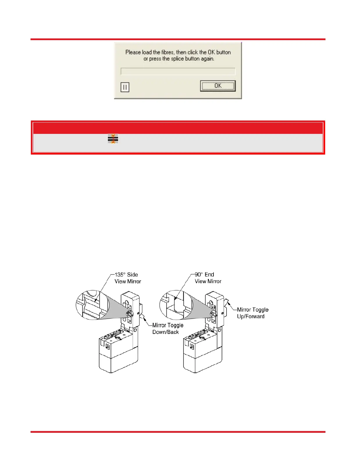
Make sure the mirror toggle is positioned with the 135° side view mirror down as shown in Figure 46 prior
to closing the splice top. Scratching of the 90° mirror can result if it is lowered onto the bar fiber in the
camera viewing area.
Figure 46 Mirror Toggle of Splice Top
After closing the Splice Cap, a live view of the fibers is displayed in the software interface. The fibers should be
roughly centered on the screen in the front and back view with a slight gap between the fiber ends, and they
should be roughly focused. If the fibers are overlapped, skewed, or completely missing from the screen, refer to
the diagnostics section at the end of this chapter for the appropriate action.
 Loading...