FFS2000 Series Chapter 11: Maintenance
Page 66 TTN047338-D02
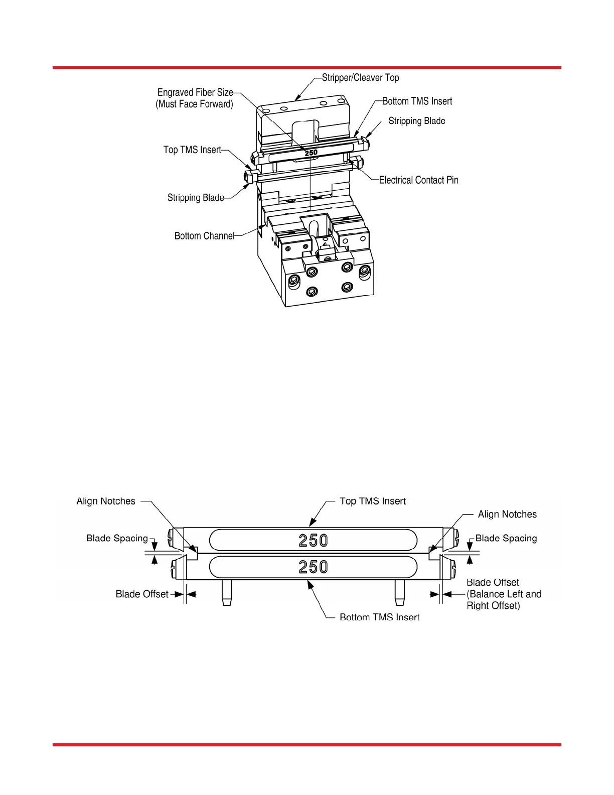
Figure 56 Removing TMS Inserts
Install New TMS Inserts
1. Position the bottom TMS insert such that the electrical contact pins line up with the two sockets in the
bottom channel and the engraved fiber size faces forward. Carefully press the pins down into the sockets
until the insert is flush with the stripper block surface.
2. Close the stripper/cleaver top.
3. Orient the top insert such that the engraved fiber size is facing forward, with the stripping blades pointing
downwards. Slide the top blade assembly into its channel, making sure the stripping blades do not touch
each other. If the top blade does not slide in easily, lift up slightly on the stripper/cleaver top.
4. Align the top TMS insert so that the offset on the right and left side between the top and bottom plates is
the same. This should correspond to aligning the “notched” edges of the top and bottom insert as shown
in Figure 57.
Figure 57 Aligning the Top TMS Insert
5. Tighten the three set screws that hold the top blade assembly. Re-check alignment, and readjust if
necessary. Note: The bottom insert is held in place by the electrical contact pins and does not need to be
secured with the set screws.
6. Check the stripping performance to confirm that the fiber is being stripped cleanly and that splice
strengths are satisfactory. If one side is not stripping cleanly, shifting the top insert to tighten up the blade
offset on that side may help.
 Loading...