Chapter 10 – Seeder Operation
85
10.4. Viewing diagnostics
Apollo ISOBUS UT seeder provides a run time view of seeder
operation through the diagnostics option.
1.
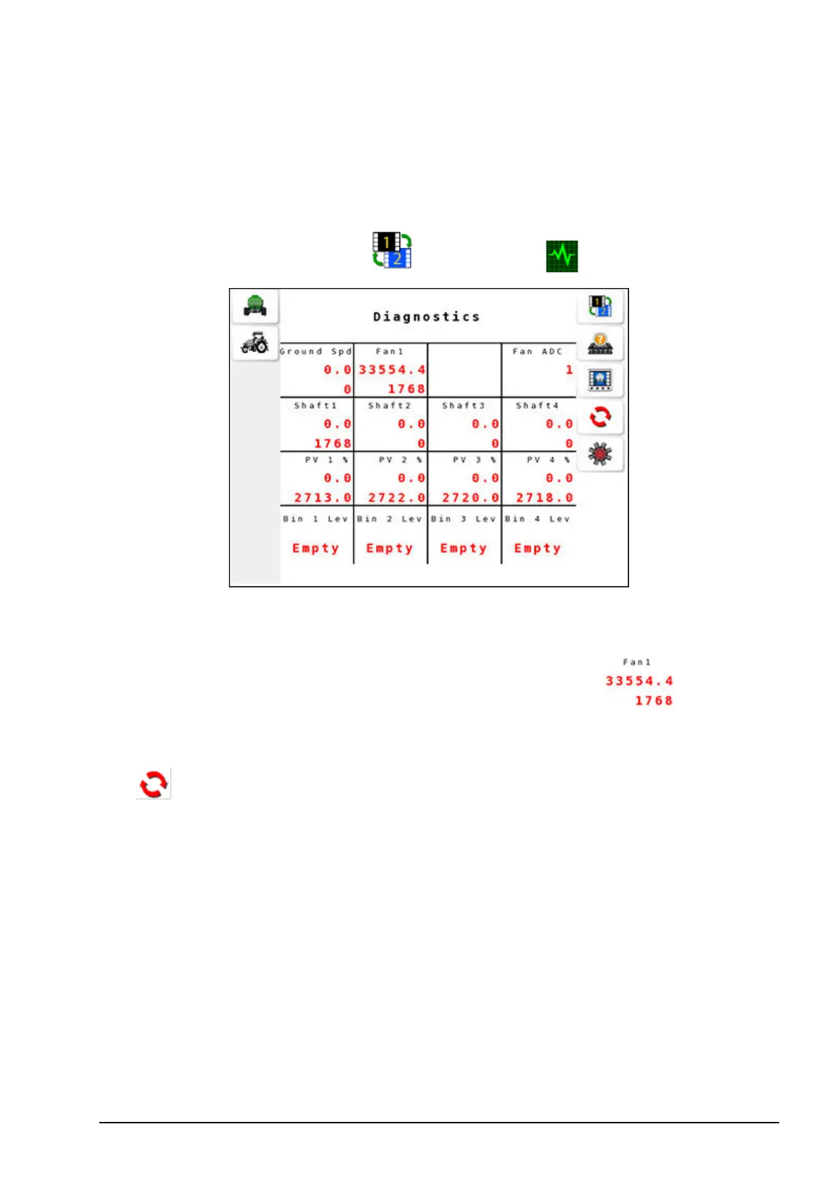
Select operation screen 2 / Diagnostics .
The diagnostics displays the time in milliseconds between pulses of
the sensor as the top value and pulse count for this sensor at the
bottom. For example, diagnostics for a fan display , where
33554.4 is the period in milliseconds and 1768 is the number of
pulses since turning on the ECU or resetting the pulses displayed (
).
l Ground Spd: Provides pulse count from the vehicle speed sensor.
l Fan #: Provides pulse count from the enabled fans.
l Shaft #: Provides pulse count from the tank shaft.
l PV #%: For proportional drives: the percentage of full power that
the valve is currently being driven. For actuator drives: the current
extension of the actuator.
l RV #%: N/A.
l Bin # Lev: Level sensor signal from the tanks.
l Fan ADC: Analog to Digital Converter for the fans.