Chapter 2 – Seeder Settings
25
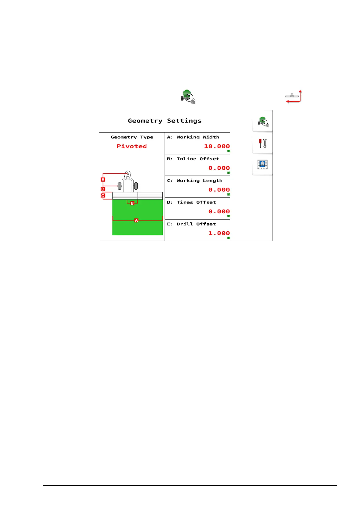
2.7. Setting up geometry
To set the implement geometry:
1.
Select Seeder Settings Menu / Geometry Settings .
l Geometry type: Select the implement type (rigid, pivoted, double
pivoted or front mount).
l Working width: Measures the working width of the implement
(that is, the width of the area that is treated during one pass of the
implement).
l Inline offset: Measures the off-center offset of the implement
relative to the hitch point. Enter a positive number if the implement
is shifted to the right and a negative number if it is shifted to the
left.
l Working length:Distance from the back of the bar/drill to the
front of the bar/drill. Note: This must be a positive number.
l Tines offset:Measures the distance from the back of the bar/drill to
the front of the bar/drill. Note: For correct product placement,
please ensure this is entered as a negative number.
l Drill offset: Measures the distance from the hitch point to the back
of the bar/drill.