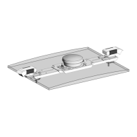
2.2. Setting up tanks
10
to drive a hydraulic motor. The opening of the valve varies with the
current applied to the solenoid.
Drive settings
l Gear ratio: The ratio between the drive motor and the metering
unit.
Note: Use the table provided on page 87 to record the gear ratio
for the P Valve drive.
l Encoder pulses/rev: Sets the number of pulses/revolutions for
each revolution of the metering shaft.
l Min shaft RPM/ max shaft RPM: Sets minimum and maximum
shaft RPM.
l Tank clutch: Enable to allow control of the tank clutch.
l Shaft sensor: When enabled sets alarm for incorrect gear ratio or
shaft jam.
l Shaft pulses/rev: Sets how many pulses the stop shaft sensor
provides per revolution.
Note: Use the table provided on page 87 to record the shaft
pulses/rev value.
Control settings
l Add dither: Enabling dither adds a small amount of current to
the solenoid of the P Valve, resulting in slight vibrations. This
prevents magnetism or sticking of the valve.
l Soft start: Allows a gradual increase in the valve signal when the
valve is activated. This is used to prevent mechanical damage
from sudden starts.
l Soft stop: Allows a gradual decrease in the valve signal when the
valve is deactivated. This is used to prevent mechanical damage
from sudden stops.
l Dump valve: Use this option if the proportional valve has its
own dump valve on each channel.