Machine Measurements and Configuration
Entering Sensor Information
39
Excavator Indicate System P/N: 1022461-01
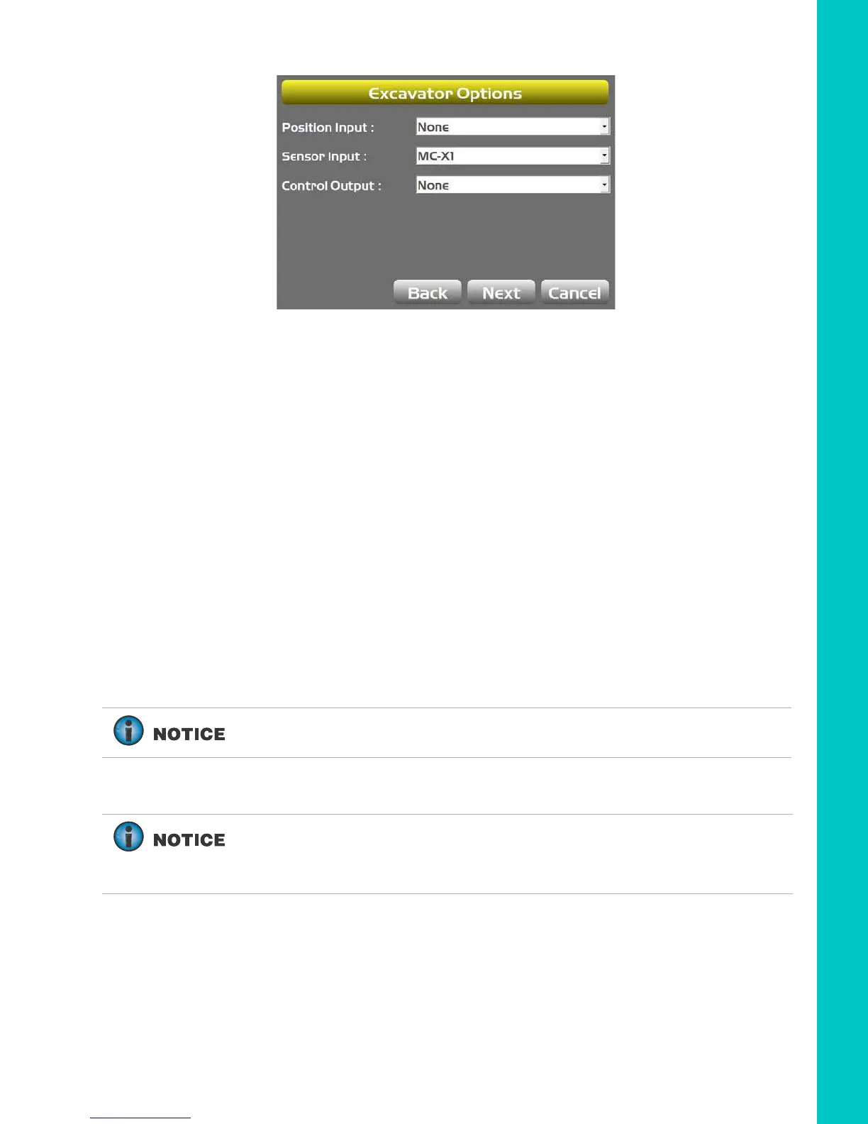
Figure 50: Select the Appropriate Position and Sensor Input
6. Enter 3D/2D sensor values:
a. For 3D systems, tap Next to navigate to the Excavator Antenna Mounting screen,
followed by the Excavator Antenna Heights screen. Enter the appropriate values as
needed on both screens.
b. For 2D systems tap Next to navigate to the Excavator IMU Mounting screen, and
select the appropriate values as needed.
Then tap Next to navigate to the Boom /
Body (1) screen. Enter the appropriate values.
7. If using a TS-i4 as a compass, select TS-i4 from the drop-down menu. Then tap the Wrench
icon to calibrate the compass. Follow the on-screen instructions.
8. Tap Next to navigate to the Boom / Body (2) screen. Enter the appropriate value.
Step 2: Designate each sensor to its corresponding implement.
If using a TS-i4, TS-i4-IMU will be selected as the Sensor ID for the body.
For the Body, Boom, Stick, and Attachment sensors, Tap the appropriate
Sensor ID box and select the serial number (last two digits) of the sensor
corresponding to the machine element. Refer to your notes from installation
to select the correct sensor ID from the drop-down menu.